Home >Technology peripherals >AI >Microsoft AR/VR patent shares solution for smart attachment of virtual keyboard
Microsoft AR/VR patent shares solution for smart attachment of virtual keyboard
- PHPzforward
- 2023-05-30 18:22:191195browse
(Nweon May 30, 2023) For XR devices, virtual keyboard is a common input method. Traditional virtual keyboards are presented near the user at a fixed angle and distance. However, sometimes users want a virtual keyboard that can intelligently move and be anchored in front of specific virtual objects based on intent, thus providing a consistent, predictable experience.
For example, in a holographic desktop office, users would like the virtual keyboard to be directly attached to the front of the virtual screen, thereby creating a configuration similar to the corresponding positional relationship between the physical keyboard and the physical screen, because the virtual keyboard and virtual screen appear together. in the same window.
In a patent application titled "Intelligent keyboard attachment for mixed reality input", Microsoft introduced a smart keyboard attachment method.
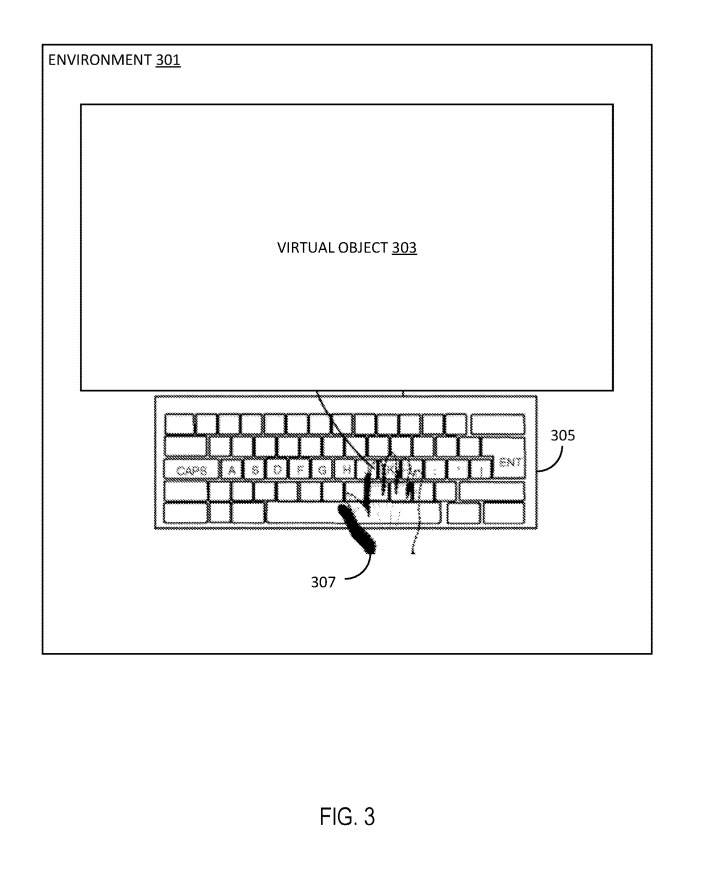
In Figure 3, virtual input device 305 is a virtual keyboard and is configured to enable input to an application corresponding to virtual object 303. When a virtual input device 305 is attached to a virtual object 303, the virtual object 303 disables other mechanisms for receiving input, such as foveated interaction and/or ray interaction.
In one embodiment, the virtual input device 305 can move within the environment 301 as the user's head moves, so that the virtual input device 305 is no longer included in the user's field of view. In other words, the virtual input device 305 can easily enter or easily leave the field of view.
Attaching the virtual input device 305 to the virtual object 303 refers to creating a hierarchical positioning transformation relationship between the virtual object 303 and the virtual input device 304 such that the virtual input device 306 inherits the position from the virtual object 303. The hierarchical positioning relationship includes one or more of distance, direction, and angle between the virtual object 303 and the virtual input device 305 .
The offset of the virtual input device 305 from the virtual object 303 provides the virtual input device with an optimal ergonomic angle. The offset between virtual object 303 and virtual input device 305 is fixed. Of course, in another implementation, the offset between virtual object 303 and virtual input device 305 may remain dynamic.
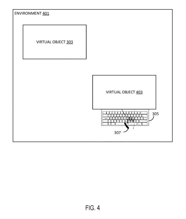
Figure 4 shows an MR environment including two virtual objects and a virtual input device.
Environment 401 includes a virtual object 303 corresponding to the first application program. At the same time, the user can open a second application program other than the first application program and generate a second virtual object 403 corresponding to the second application program.
Like the virtual object 303, the second virtual object 403 is provided at a specific location within the three-dimensional environment 401. In response to the determination of the user's intention to utilize the virtual input device 305 with the second virtual object 403 , the second virtual object 403 repositions the virtual input device 305 to a position closer to the second virtual object 403 .
For example, the determination of intent may be based on user selection of a button on virtual input device 305, such as a query button, to indicate that user input with respect to virtual object 403 is intended or expected.
In response to the determination, the virtual input device 305 is detached from the original position proximate the virtual object 303 and reattached to the second virtual object 403 at a new position proximate the second virtual object 403 .
In an implementation where the user switches back to the first application corresponding to virtual object 303, virtual input device 305 is relocated to the original position close to virtual object 303.
In other words, the virtual input device 305 is provided at the virtual object with which the user desires to interact at a specific point in time.
Microsoft states that this configuration provides users with a consistent, predictable experience and is dependent on the specific application being used, rather than the user's location in the three-dimensional environment 301, 401.
The specific application the user wants to interact with is identified through various mechanisms.
In one embodiment, the specific application the user intends to interact with is based on the current virtual object or panel the user is interacting with. For example, where virtual object 303 is a contact list, the input may search for a contact in the contact list. In the case where virtual object 303 is a work application, the input may search the work application for keywords or documents. In the case where the virtual object 303 is an incident reporting application, the input may be an explanation for filling out the incident report.
So, the virtual input device 305 is an intelligent input device that can be detached from a specific virtual object based on the user's intention.
In one embodiment, input from an intent that separates virtual input device 305 from virtual object 303 may be received. The input may be input received via the virtual input device 305, a gaze pattern determined by the highlight 200, a selection of the UNDOCK detached icon on the virtual object 303, 403, input to a specific button on the virtual input device 304, etc.
The detachment, that is, the undocking, of the virtual input device 305 from the virtual object 303 enables the virtual input device to switch between different virtual objects in the environment 301, 401 while the user remains stationary. Once the virtual input device 305 is attached, visual cues or visual aids are provided.
In one embodiment, virtual input device 305 is detached or undocking from virtual object 303 and removed from environment 401 . On the next call, virtual input device 305 is re-instantiated in environment 401 attached to virtual object 303 .
In other embodiments, the virtual input device 305 is detached from the virtual object 303 but remains in the environment 401 and attached to the new and/or next virtual object 403 . In another SSL, virtual input device 305 is detached from virtual object 303 but remains in environment 401 and remains at a specific location within environment 410.
In another embodiment, the virtual input device 305 is detached from the virtual object 303 but remains in the environment 401 with an offset close to the user. For example, the virtual input device 305 may be held slightly in front of and to the left or right of where the user is located based on the position and orientation of the headset.
The separate virtual input device 305 can be invoked to the user or specific virtual objects 303, 403, such as through voice commands or other mechanisms. Wherein, the virtual input device 305 is located far away from the user and enables the user to quickly bring the virtual input device 304 to them without having to move to retrieve the virtual input device 306, and the virtual input device 307 is passively moved closer to the user's convenience , ready-to-use ergonomic position.
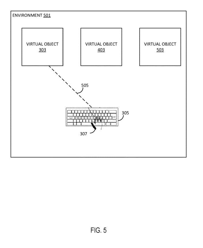
Figure 5 shows a multi-target environment. Environment 501 includes a plurality of virtual objects, such as virtual objects 303, 403, 503. For example, environment 501 may be a virtual desktop environment and include different virtual objects 303, 403, 503, each virtual object corresponding to a different application within the virtual desktop.
For example, virtual object 303 may be a messaging application, virtual object 403 may be an Internet browser application, and virtual object 503 may be a contacts application.
Each virtual object 303, 403, 503 is a separate target of the virtual input device 305. In situations such as where the user may periodically switch between providing input to virtual objects 303, 403, 503, the user may desire virtual input device 305 to be attached to a specific location, such as close to the user, and act as a near-field floating input device.
Therefore, a visual link 505 between the virtual input device 305 and the target virtual object may be provided. For example, FIG. 5 shows a visual link 505 between virtual input device 305 and virtual object 303 indicating that, at a particular time, input received on virtual input device 304 will generate input to virtual object 303 .
In one embodiment, visual link 505 is a virtual object, such as a line, that connects virtual input device 305 to a target virtual object and improves consistent understanding of user input. In other implementations, the visual link is a visual marker on the target virtual object, such as a sticker, star, dot, etc.
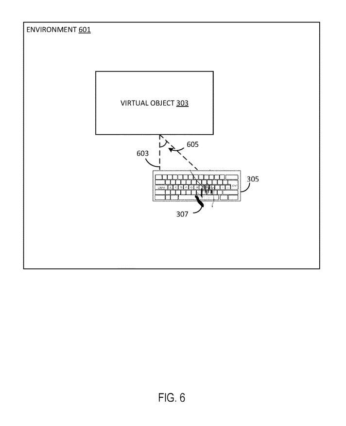
Figure 6 shows the offset between virtual objects and virtual input devices.
As shown in Figure 6, the virtual input device 305 is provided at a certain distance 603 from the virtual object 303. When any one of the virtual object 303 and the virtual input device 305 moves, a distance 603 is maintained between the virtual object 303 and the virtual input device.
In other words, if the virtual object 303 moves a specific distance from its original location, the virtual input device 305 also moves a specific distance from its original location to maintain the distance 603 between the virtual object 303 and the virtual input device 304.
Similarly, if virtual input device 305 moves a specific distance from its original location, virtual object 303 also moves a specific distance from its original location to maintain distance 603 between virtual object 303 and virtual input device 304.
Distance 603 is based at least in part on the particular type of input device represented by virtual input device 305. For example, a virtual keyboard is similar to a physical keyboard, with similar sizes and shapes.
When the virtual object 303 is moved, the virtual input device 305 may move with the virtual object 303 or follow the virtual object 303 to maintain the distance 603 and angle 605 between the virtual object 303 and the virtual input device 303. Accordingly, an offset between virtual object 303 and virtual input device 305 may be provided in various embodiments.
Figures 7A-7D illustrate changing fields of view for virtual objects and virtual input devices.
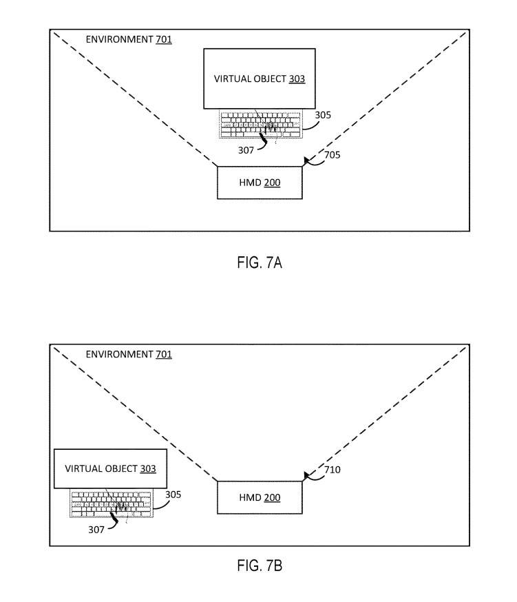
As shown in Figure 7A, the virtual object 303 and the virtual input device 305 are completely within the first field of view 705. In other words, each of virtual object 303 and virtual input device 305 is in the user's full view.
In Figure 7B, each of the virtual object 303 and the virtual input device 305 is completely outside the second field of view 710. The field of view changes from a first field of view 705 to a second field of view 710 . For example, the user moves his or her head causing the headset to move, which changes, updates, changes, etc. from a first field of view 705 to a second field of view 710 . In other implementations, the field of view itself may not have changed, but virtual object 303 and virtual input device 305 may have moved outside the field of view, such as by the user inadvertently dragging virtual object 303 and virtual input device 305 into the first field of view. Beyond 705.
Therefore, the second field of view 710 presents a challenge because the user cannot view the virtual object 303 and the virtual input device 305 , which makes providing input to the virtual object 303 via the virtual input device 304 challenging.
Therefore, the removal of virtual object 303 and virtual input device 305 from the field of view can be corrected using the method described in the patent.
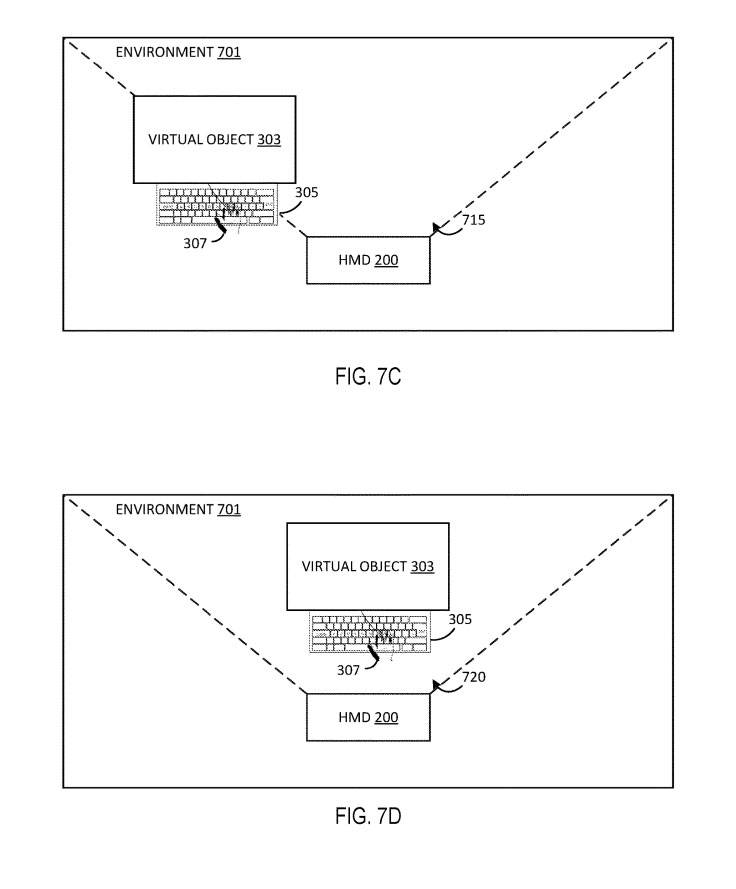
Figure 7C shows a third field of view 715 in which virtual object 303 and virtual input device 305 are gradually reintroduced into the field of view. Rather than virtually instantaneously snapping virtual objects 303 and virtual input devices 305 back to their original positions within the field of view, virtual objects 303 and virtual input devices 305 are gradually reintroduced into the field of view in order to maintain a more comfortable experience for the user.
Figure 7D shows the fourth field of view 720 after the virtual object 303 and the virtual input device 305 have been placed back into the field of view. The fourth field of view 720 is substantially similar to the first field of view 705 in that the virtual object 303 and the virtual input device 305 have been returned to their original positions in the first field of view 705 .
Related Patents: Microsoft Patent | Intelligent keyboard attachment for mixed reality input
Microsoft’s patent application titled “Intelligent keyboard attachment for mixed reality input” was recently published by the United States Patent and Trademark Office.
The above is the detailed content of Microsoft AR/VR patent shares solution for smart attachment of virtual keyboard. For more information, please follow other related articles on the PHP Chinese website!
Related articles
See more- Technology trends to watch in 2023
- How Artificial Intelligence is Bringing New Everyday Work to Data Center Teams
- Can artificial intelligence or automation solve the problem of low energy efficiency in buildings?
- OpenAI co-founder interviewed by Huang Renxun: GPT-4's reasoning capabilities have not yet reached expectations
- Microsoft's Bing surpasses Google in search traffic thanks to OpenAI technology

