Home >Technology peripherals >AI >Microsoft AR/VR patent sharing solves occlusion or parallax problems caused by different camera angles
Microsoft AR/VR patent sharing solves occlusion or parallax problems caused by different camera angles
- 王林forward
- 2023-11-03 12:29:021374browse
(Nweon November 3, 2023) Since the position cannot correspond to the eyes, for a head-mounted display based on camera perspective, it may be difficult for users to correctly perceive the spatial relationship of objects in the environment relative to the defined space. Additionally, multiple users within the same defined space may have different perspectives relative to objects outside the defined space.
So in the patent application titled "Perspective-dependent display of surrounding environment", Microsoft proposes an environment image that correctly represents the defined space, especially in a mobile platform like a car. In short, the computing system constructs a depth map and intensity data of at least a portion of the environment surrounding a defined space. The intensity data is then correlated with the depth map location.
Additionally, the computing system may obtain information about the user's posture within the defined space and determine, based on the user's posture, a portion of the surrounding environment of the defined space that the user is looking at. The computing system further obtains image data representing portions of the environment from the user's perspective,
Then, the computing system generates an image for display based on the intensity data at the depth map location within the user's field of view. In this way, the view of the environment obtained by one or more cameras can be reprojected to the user's perspective, providing a correct view of the environment without occlusion or parallax issues due to the different perspectives of the cameras.
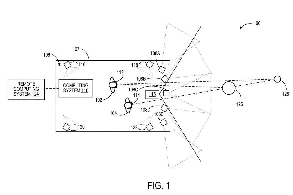
Figure 1 illustrates an exemplary usage scenario 100 in which users 102 and 104 are located within a defined space 106. Users 102 and 104 wear head-mounted devices 112 and 114, respectively.
The computing system 110 generates image data representing the environment surrounding the defined space from the perspective of each user 102, 104. To do this, computing system 110 obtains information about the posture of each user 102 and 104 in defined space 106 .
In one embodiment, the pose of each user 102, 104 may be determined from one or more imaging devices fixed in a reference frame of the defined space and configured to image the user within the defined space.
In Figure 1, four such imaging devices are depicted as 116, 118, 120 and 122. Examples of such imaging devices may include stereo camera devices, depth sensors, and the like.
Computing system 110 may be configured to generate a depth map of the environment surrounding defined space 106 from data from cameras 108A-108E. Each camera 108A-108E is configured to acquire intensity image data of a portion of the surrounding environment. The cameras all know their spatial relationship to each other.
In addition, as shown in Figure 1, the fields of view of adjacent cameras overlap. Therefore, stereo imaging techniques can be used to determine the distance of objects in the surrounding environment to generate depth maps. In other examples, an optional depth sensor 115 separate from the cameras 108A-108E may be used to obtain a depth map of the surrounding environment. Example depth sensors include lidar sensors and one or more depth cameras. In such an example, the fields of view of the cameras that optionally acquire intensity images may not overlap.
Intensity data from the camera is associated with each location in the depth map, such as each vertex in a mesh or each point in a point cloud. In other examples, intensity data from the cameras are computationally combined to form calculated combined intensity data for each location in the depth map. For example, when a depth map location is imaged by sensor pixels from two or more different cameras, the pixel values from the two or more different cameras can be calculated and then stored.
Next, based at least on the gesture of each user 102, 104, the computing system 110 may determine a portion of the environment surrounding the defined space that each user 102, 104 is looking at, obtaining a representation from the perspective of each user 102, 104 Image data of this part of the environment, and provide the image data to each head display 112, 114.
For example, by knowing the user's posture within the defined space 106, and the spatial relationship between the depth map of the surrounding environment and the defined space 106, each user's posture can be associated with the depth map. Each user's field of view can then be defined and projected onto the depth map to determine the portion of the depth map that is within the user's field of view.
Next, techniques like ray casting can be used to determine the locations in the depth map that are visible within the field of view. Intensity data associated with the location can be used to form an image for display. Computing system 110 may optionally communicate with a remote computing system 124 such as a cloud service. In such instances, one or more of such processing steps may be performed by remote computing system 124.
In this way, within a certain space, different users can observe images of the surrounding environment from a personal perspective. The image displayed by headset 112 from the perspective of user 102 may include object 126 and a view of object 128 in the environment, while the view of object 128 may be occluded by object 126 in the image displayed by headset 114 from the perspective of user 104 .
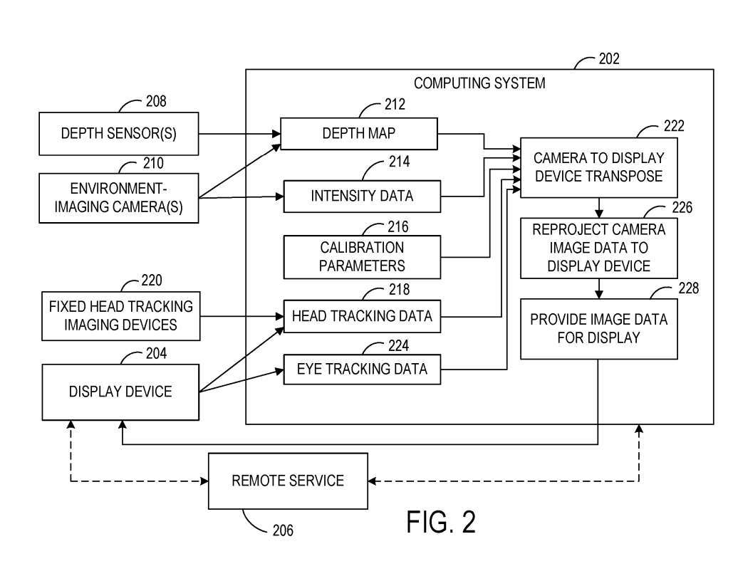
Figure 2 shows a block diagram of an example system 200 configured to display an image of the environment surrounding a defined space to a user within the defined space from the user's perspective. System 200 includes a computing system 202 local to a defined space and a display device 204 located within the defined space.
System 200 includes one or more cameras 210 and is configured to image the environment. In one example, camera 210 is used as a passive stereo camera and uses stereo imaging methods to acquire intensity data and depth data. In other examples, one or more depth sensors 208 are optionally used to obtain depth data of the surroundings of a defined space.
Computing system 202 includes executable instructions for constructing a depth map 212 of the environment from the depth data. Depth map 212 may take any suitable form, such as a 3D point cloud or mesh. As described above, computing system 202 may receive and store intensity data 214 associated with each location in depth map 212 based on image data acquired by one or more cameras 210 .
The relative spatial positions of the depth sensor 208 and the camera 210 are calibrated to each other and to the geometry of the defined space. Accordingly, FIG. 2 illustrates calibration parameters 216 that may be used as input to help transpose the view of the camera 210 and depth sensor 208 to the user's posture, thereby helping to reproject the image data from the camera perspective to the user perspective for display. .
In one embodiment, because the display device 204 and/or the defined space may continually move relative to the surrounding environment, a continuous external calibration may be performed to calibrate the position of the display device 204 to the depth map 212 . For example, calibration of depth map 212 by display device 204 may be performed at a frame rate of display by display device 204 .
The computing system 202 may further obtain information about the user's posture within the defined space. A user's posture can more specifically refer to head position and head orientation, which helps determine part of the environment surrounding the defined space the user is looking for. Computing system 202 is configured to receive head tracking data 218 . Head tracking data 218 may additionally or alternatively be received from one or more imaging devices fixed in a frame of reference in a defined space.
As described above, computing system 202 uses depth map 212 and corresponding intensity data 214 in conjunction with the user's posture determined from head tracking data 218 to determine image data for display from the perspective of the user of display device 204 .
The computing system 202 may determine the part of the environment that the user is looking at based on the user's posture, project the user's field of view onto the depth map, and then obtain intensity data for the depth map locations visible from the user's perspective.
Image data provided to the display device for display may undergo post-reprojection within the frame buffer of the display device 204. For example, post-reprojection can be used to update the position of objects in a rendered image directly before the rendered image is displayed.
Here, display device 204 is located in a moving vehicle, and the image data in the frame buffer of display device 204 may be reprojected based on the distance traveled by the vehicle between image formation and image display at 226. Computing system 202 may provide motion vectors to display vehicle motion-based device 204 for later reprojection. In other examples, motion vectors may be determined from data from a local inertial measurement unit of display device 204 .
In one embodiment, the frame rate of the intensity data acquired by the camera 210 may be different from the frame rate of the depth map acquired by the depth sensor 208. For example, the frame rate used to acquire depth maps may be lower than the frame rate used to acquire intensity data.
Likewise, frame rate may vary based on changes in vehicle speed, moving objects in the environment, and/or other environmental factors. In such examples, before associating the intensity data with the depth map location, the intensity data and/or depth data may be translated to correct for motion that occurs between the time the intensity data is obtained and the time the depth map is obtained.
Where multiple cameras 210 are used to acquire intensity data, objects in the environment surrounding the defined space may appear in the image data from the multiple cameras 210 . In such an example, the intensity data from each camera imaging the object can be reprojected to the user's perspective.
In other examples, intensity data from one camera or subset of cameras imaging the object can be reprojected to the user's perspective. This may use less computing resources than transposing the image data from all cameras imaging the object to the user's perspective.
In such an example, image data from a camera with a perspective determined to be closest to the user's perspective may be used. In another example, pixel intensity data from multiple cameras for a selected depth map location may be averaged or otherwise computationally combined and then stored for the depth map location.
In the example of FIG. 1 , users 102 and 104 view perspective-dependent images generated by computing system 110 through headsets 112 , 114 . In the exemplary scenario 300 of FIG. 3, a user is viewing image data acquired by cameras 306A-306E on a display panel located at a fixed location within a defined space 304.
However, instead of displaying images from the perspective of cameras 306A-306E, the image data from cameras 306A-306E is associated with a depth map determined from the image data, or a depth map determined from data obtained from a depth sensor. Union.
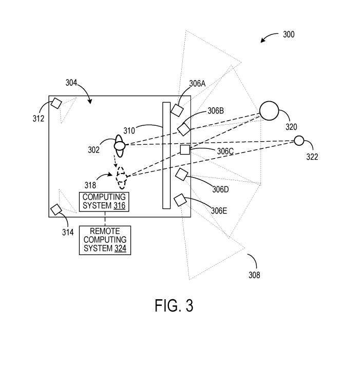
This allows the image data to be converted into a perspective view of the user 302. Cameras 312, 314 image the interior of defined space 304 to perform user gesture tracking. One or more depth sensors are additionally used for user posture determination. Image data from the perspective of user 302 may be displayed on display panel 310 based on user gesture data determined from data from cameras 312, 314.
In this example, reprojecting the image data to the perspective of the user 302, in addition to the operations described above with respect to Figure 2, may also include user gestures to display panel transposition because the user 302 is The location changes as the user moves within the defined space 304.
Thus, when user 302 moves to a new location 318, objects 320, 322 in the environment will appear from a different angle than user 302's original location. Computing system 316 optionally can communicate with a remote computing system 324 such as a cloud service.
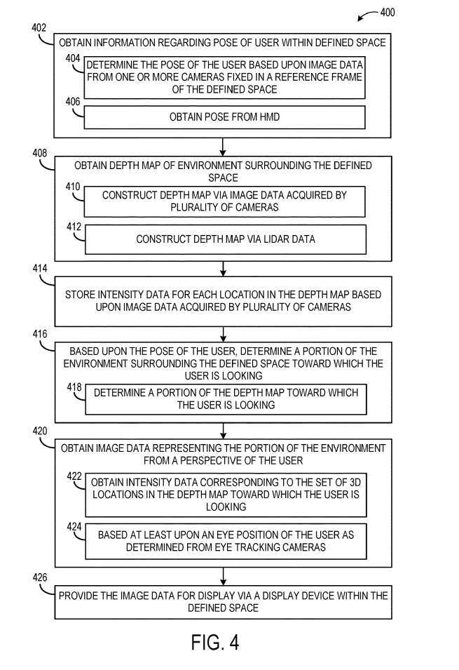
Figure 4 illustrates an example method 400 of providing image data of an environment surrounding a defined space for display from the perspective of a user within the defined space.
At 402, method 400 includes obtaining information about the user's posture within the defined space. As mentioned above, for example, a user's posture may reflect head position and orientation. The user's gesture may be determined based on image data from one or more cameras fixed in a spatial reference frame. As another example, at 406, the user's gesture may be received from a headset worn by the user, for example, determined from image data from one or more image sensors of the headset.
At 408, include obtaining a depth map of the environment surrounding the defined space. The depth map may be constructed from image data acquired by multiple cameras imaging the environment at 410, or may be constructed from lidar data acquired by a lidar sensor at 412.
In other examples, other suitable types of depth sensing may be utilized, such as time-of-flight depth imaging. Then at 414, method 400 includes storing intensity data for each location in the depth map.
Next at 416, based on the user's posture, a portion of the environment surrounding the defined space that the user is seeking is determined. This may include determining at 418 which portion of the depth map the user is looking at. In one example, the user's field of view can be projected onto the depth map to determine the location in the depth map that is visible from the user's perspective.
Method 400 also includes, at 420, obtaining image data representing the portion of the environment from the user's perspective. Method 400 also includes, at 426, providing image data for display by a display device within the defined space.
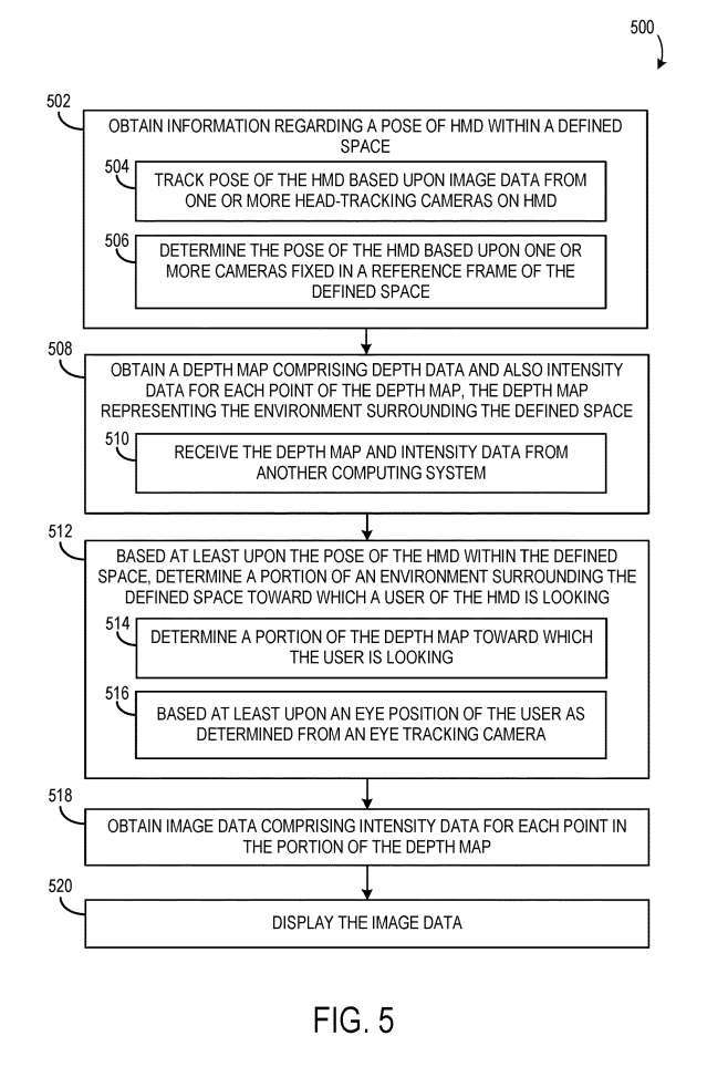
Figure 5 shows a flowchart of an example method 500 for displaying environmental image data from a user's perspective through a head-mounted display.
At 502, method 500 includes obtaining information about the pose of the headset within the defined space. The pose of the headset can be tracked based on image data from one or more of the headset's head-tracking cameras. At 504, the pose of the headset may be determined based on one or more cameras fixed in a reference frame that defines the space. At 506, one or more fixed cameras communicate with the headset.
At 508, method 500 also includes obtaining a depth map, which includes depth data and intensity data for each position of the depth map, where the depth map represents the environment surrounding the defined space.
At 512, based at least on the pose of the headset within the defined space, a portion of the environment surrounding the defined space that the user of the headset is looking at is determined. This may include, at 514, determining the portion of the depth map that the user is looking at. The portion of the environment/depth map that the user is looking at may further be based at least on the user's eye position.
The method 500 further includes, at 518, obtaining image data including intensity data for each location in the depth map portion, and at 520, displaying the image data.
Related Patents: Microsoft Patent | Perspective-dependent display of surrounding environment
The Microsoft patent application titled "Perspective-dependent display of surrounding environment" was originally submitted in March 2022 and was recently published by the US Patent and Trademark Office.
The above is the detailed content of Microsoft AR/VR patent sharing solves occlusion or parallax problems caused by different camera angles. For more information, please follow other related articles on the PHP Chinese website!
Related articles
See more- Technology trends to watch in 2023
- How Artificial Intelligence is Bringing New Everyday Work to Data Center Teams
- Can artificial intelligence or automation solve the problem of low energy efficiency in buildings?
- OpenAI co-founder interviewed by Huang Renxun: GPT-4's reasoning capabilities have not yet reached expectations
- Microsoft's Bing surpasses Google in search traffic thanks to OpenAI technology

