改進自動駕駛在不確定環境下的軌跡規劃方法
- WBOYWBOYWBOYWBOYWBOYWBOYWBOYWBOYWBOYWBOYWBOYWBOYWB轉載
- 2023-10-06 14:17:031157瀏覽
论文题目:《基于改进的模型预测控制的自动驾驶车辆在不确定环境下的轨迹规划方法》
发表期刊:IEEE Transactions on Intelligent Transportation Systems
发布日期:2023年04月
以下是我自己的論文閱讀筆記,主要是我自己覺得重點的部分,非全文翻譯,該文章接著前一篇文章,梳理了本論文的實驗驗證部分。前一篇文章如下: 以下是我自己的論文閱讀筆記,主要是我自己覺得重點的部分,非全文翻譯,該文章接著前一篇文章,梳理了本論文的實驗驗證部分。前一篇文章如下:
fhwim:一种针对不确定环境下自动驾驶车辆的基于改进的模型预测控制的轨迹规划方法
https://zhuanlan.zhihu.com/p/658708080
1. 仿真验证
(1)仿真环境
联合仿真工具包括Prescan、PyCharm、Matlab/Simulink,其中Prescan用于搭建仿真的交通场景,PyCharm(有神经网络还是用pytorch轻松)用来写融合预测模块,Matlab/Simulink(有MPC工具箱)用来搭建轨迹规划模块以及实现车辆控制,整体工具的选择思路还是比较自然合理。控制这一部分横向控制用的是LQR,纵向控制用的是PID,也是比较常用的控制方法。融合预测模块中的LSTM encoder-decoder采用的是开源代码,作者说来自参考文献[31]Comprehensive Review of Neural Network-Based Prediction Intervals and New Advances这篇文章,但是我看这篇文章发表于2011年,有点久远(2011就有LSTM encoder-decode呢?),不知道作者有没有在此基础上改代码。
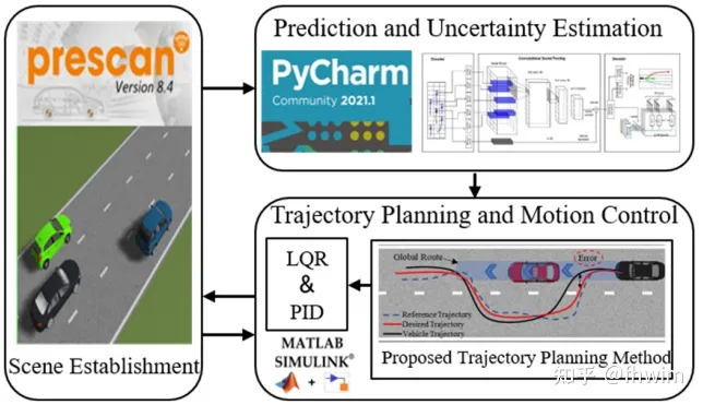
图1 仿真环境搭建
(2)MRPI集的求取


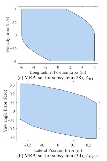
图2 子系统的MRPI集
(3)case1:静态避障场景
静态避障场景指一辆障碍车静止不动,轨迹规划结果如下图:
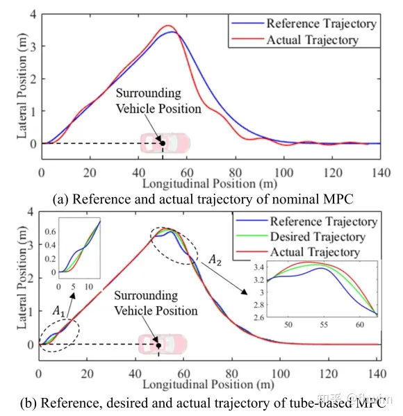
对比图3中一般的MPC方法和基于管道的MPC方法
这里我怀疑他图例有问题,按照前文,最终参考轨迹reference trajectory由期望轨迹desired trajectory 和调整轨迹adjustment trajectory相加得到,同时他在分析结果的时候也说tube-based MPC在图3(b)区域 和 的误差较大,由于adjustment trajectory减小了误差,那应该是把图3(b)的desired trajectory和reference trajectory两个图例交换一下才符合他这个文章的逻辑,也就是绿线是最终的reference trajectory,蓝线是中间结果desired trajectory。包括下面的速度曲线、横纵向误差曲线也是,不过大概懂作者意思就行,tube-based MPC中绿色曲线是最终的结果,蓝色曲线是未加adjustment trajectory的结果。
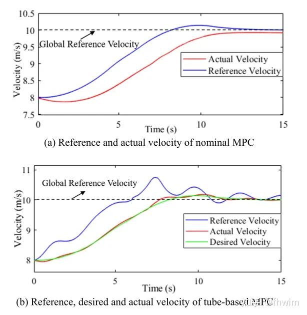
图4展示了一般MPC方法和基于管道的MPC方法在速度变化方面的对比
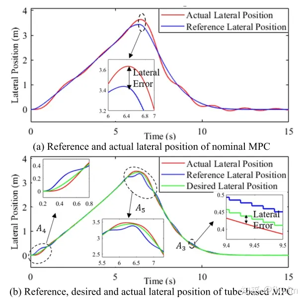
图5 横向位置对比
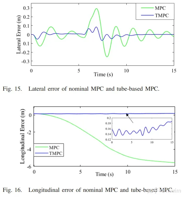
需要进行改写的内容是:比较横纵向误差的图6
作者也對方向盤角度變化的平穩程度進行了比較,這裡就不再詳述,總之有所改善。同時,作者提出了調整軌跡效果良好的理論依據,加入後,軌跡誤差始終在MRPI集合內,也就是說基於管道的模型預測控制(tube-based MPC)的追蹤偏差一直保持在MRPI集合內,而一般的模型預測控制(MPC)在不確定環境下沒有邊界,可能會很大
(4)case2:動態避障場景
與先前的場景相比,現在障礙車開始運動了。對於整體軌跡、速度變化、橫縱向誤差以及方向盤變化的平穩性等方面,不再贅述。在這裡,只展示一個整體軌跡的圖示
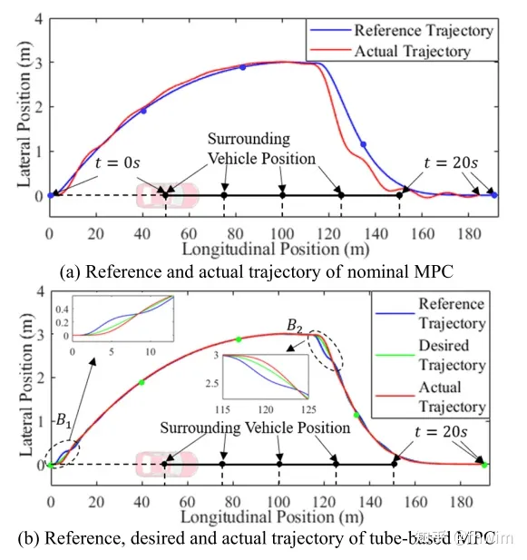
圖7 一般MPC方法和tube-based MPC方法的整體軌跡對比
(5) case3:真實駕駛場景
在這裡,作者選擇使用NGSIM資料集來驗證自己的方法。首先,作者驗證了融合預測方法。 NGSIM資料集包含了車輛的軌跡數據,作者將其拆分為歷史軌跡和未來軌跡,並建立了一個訓練集,以便LSTM編碼器-解碼器進行學習。作者選擇了10000條軌跡,其中7500條用作訓練集,2500條用作驗證集。優化器採用了Adam,並將學習率設為0.01。預測效果如下圖所示
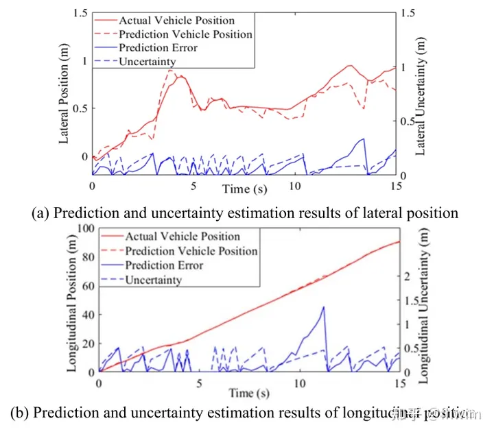
圖8 橫縱向上軌跡預測與不確定性的結果
作者在這篇文章中並沒有使用軌跡預測領域常用的指標,如ADE、FDE等。我認為這樣的做法缺乏說服力,但也可以理解本文的重點在於基於基於tube-based MPC的軌跡規劃
在驗證完軌跡預測後又進行了軌跡規劃進一步驗證軌跡預測模組的作用,這裡是比較了三種情況:
(a)在我已經知道障礙車未來真實軌蹟的情況下,我去進行軌跡規劃,這個作為對照組
在我不在知道障礙車未來軌跡的情況下,我先進行軌跡預測(但不計算不確定性),然後再進行軌跡規劃
(c)在我不知道障礙車未來軌跡的情況下,我先進行軌跡預測(計算不確定性),再進行軌跡規劃
圖9顯示了(a)、(b)和(c)的結果,分別對應True Position,Prediction Results和Proposed Method
Proposed Method 也就是本文的方法所得出的結果,可以看到Proposed Method更接近True Position,說明這個融合預測方法(尤其是不確定性的計算)是有作用的。
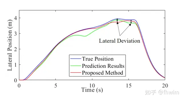
圖9 三種方法比較驗證軌跡預測模組
這裡可以發現case1和case2驗證的是軌跡規劃部分,一般的模型預測控制( MPC)和基於管道的MPC前面的軌跡預測部分是一樣的,這樣比較可以說明基於管道的MPC的作用。 case3則是驗證軌跡預測模組,可以看到進行了兩類驗證。第一類是直接比較預測軌跡和真實軌跡,第二類是先已知未來軌跡/預測未來軌跡(不計算不確定性)/預測未來軌跡(計算不確定性),然後再進行軌跡規劃。以真實位置為標準,比較有不確定性計算的軌跡預測方法和沒有不確定性計算的軌跡預測方法的效果。對這兩個模組的驗證思路還是很清晰的
2. 實車實驗驗證
實驗所用車輛如下圖所示:
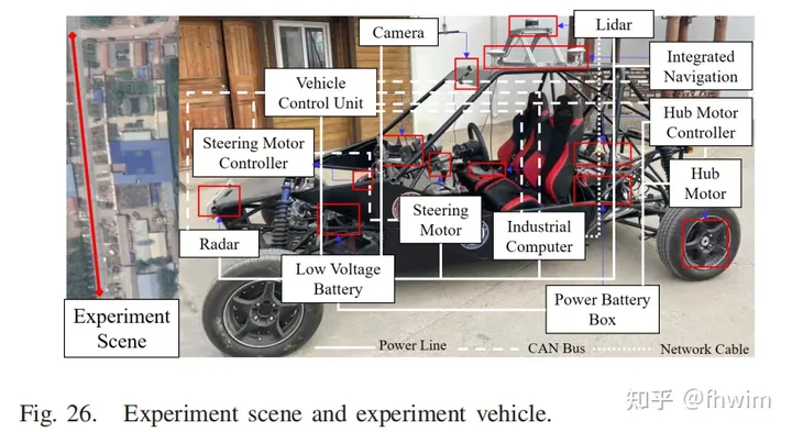
#需要重新寫作的內容是:實驗中使用的車輛的圖片10
作者還提供了實驗車輛的參數以及實驗中使用的電腦和感測器的參數:
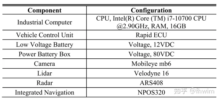
需要重寫的內容是:圖11 電腦和感測器的參數
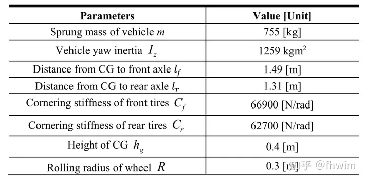
需要重新寫的內容是:實驗車輛的參數,圖12
For the sake of safety, the experimental scene set up by the author is the same as the simulation experiment case 1. It is a static obstacle avoidance scene. It is still a comparison of the overall trajectory, speed changes, horizontal and vertical errors, and the smoothness of steering wheel changes, which will not be described again.
3. Reading summary
First of all, the idea of the paper is about the trajectory prediction module with uncertainty calculation and the trajectory planning module based on tube-based MPC. Among them, the trajectory planning module is the main content. I am very satisfied with this modular form because it truly applies trajectory prediction to trajectory planning. The output of prediction is used as the input of planning, and the planning module only determines a safety threshold for the prediction module, and the coupling between the two modules is weak. In other words, the prediction module can be replaced by other methods as long as it can provide the results of predicting the trajectory and uncertainty of the obstacle car. In the future, more advanced neural networks could be considered to directly predict trajectories and uncertainties. Overall, the process of this fusion prediction algorithm is a bit complicated, but I think the idea of the paper is very good. The ideas and workload of simulation and real vehicle testing are also satisfactory
The second is some low-level errors discovered when reading the article. For example, in the LSTM encoder-decoder part, LSTM outputs the trajectory points of steps in the future, which is also written in the formula, but in the text it is written as .

Figure 13 Some errors in the LSTM encoder-decoder part
Then in the simulation experiment part, when calculating the MRPI Set, it says system (21), which is error The system is divided into subsystems (32) and (34), but it is actually subsystems (30) and (32). These small errors do not affect the overall method but will also affect the reader's reading experience.

Figure 14 Simulation experiment part MRPI Set original text
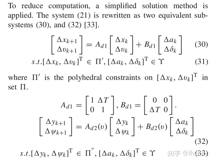
The error system in Figure 15 is divided into subsystems ( 30) and (32)

Original link: https://mp.weixin.qq.com/s/0DymvaPmiCc_tf3pUArRiA
以上是改進自動駕駛在不確定環境下的軌跡規劃方法的詳細內容。更多資訊請關注PHP中文網其他相關文章!

