
Home >Web Front-end >H5 Tutorial >Introduction to SVG 2D in HTML5 2—Introduction and use of graphic drawing (basic shapes)_html5 tutorial skills
Introduction to SVG 2D in HTML5 2—Introduction and use of graphic drawing (basic shapes)_html5 tutorial skills

- WBOYWBOYWBOYWBOYWBOYWBOYWBOYWBOYWBOYWBOYWBOYWBOYWBOriginal
- 2016-05-16 15:50:051848browse
Basic shapes
SVG provides a lot of basic shapes. These elements can be used directly, which is much better than canvas. Stop talking nonsense and look at the example directly. This is the most direct:
The result displayed by this HTML is as follows:
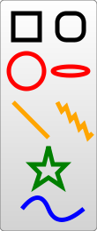
This example draws many shapes: normal rectangle, rectangle with rounded corners, circle, ellipse, straight line, polyline, polygon, and path. These are basic graphic elements. Although there are many ways to draw a graphic, for example, a rectangle can be implemented using rect or path, etc., we should still try to keep the content of SVG short, concise and easy to read .
The following are instructions for using each shape (here we only introduce the basic attributes that control the shape and position of graphics, and attributes such as filling will be summarized later).
Rectangle - rect element
This element has 6 attributes that control position and shape, which are:
x: the coordinates of the upper left corner of the rectangle (user coordinates system) x value.
y: The y value of the coordinates of the upper left corner of the rectangle (user coordinate system).
width: rectangle width.
height: rectangle height.
rx: When achieving the rounded corner effect, the radius of the rounded corner along the x-axis.
ry: When achieving the rounded corner effect, the radius of the rounded corner along the y-axis.
For example, in the above example, the rounded corner effect is achieved. You can also achieve the elliptical corner effect by setting rx and ry to different values.
Circle - circle element
The attributes of this element are very simple, mainly defining the center and radius of the circle:
r: the radius of the circle.
cx: circle center coordinate x value.
cy: circle center coordinate y value.
Ellipse - ellipse element
This is a more general circular element. You can control the length of the semi-major axis and semi-minor axis separately to realize different ellipses. , it is easy to think that when the two semi-axes are equal, it is a perfect circle.
rx: semi-major axis (x radius).
ry: semi-minor axis (y radius).
cx: circle center coordinate x value.
cy: circle center coordinate y value.
Straight line - line element
A straight line needs to define the starting point and end point:
x1: x coordinate of starting point.
y1: y coordinate of the starting point.
x2: x coordinate of the end point.
y2: y coordinate of the end point.
Polyline - polyline element
Polyline mainly defines the endpoints of each line segment, so only a collection of points is needed as a parameter:
points: A series of points separated by spaces, commas, newlines, etc. Each point must have 2 numbers: x value and y value. So the following three points (0,0), (1,1) and (2,2) can be written as: "0 0, 1 1, 2 2".
Polygon - polygon element
This element does one more step than the polyline element, connecting the last point to the first point to form a closed figure. The parameters are the same.
points: A series of points separated by spaces, commas, newlines, etc. Each point must have 2 numbers: x value and y value. So the following three points (0,0), (1,1) and (2,2) can be written as: "0 0, 1 1, 2 2".
Path - path element
This is the most versatile and powerful element; using this element you can realize any other graphics, not only the above basic Shape can also achieve complex shapes like Bezier curves; in addition, using path can achieve smooth transition line segments. Although polyline can also be used to achieve this effect, there are many points that need to be provided, and the enlargement effect is not good. good. This element controls position and shape with only one parameter:
d: a series of drawing instructions and drawing parameters (points) combined.
Drawing instructions are divided into two types: absolute coordinate instructions and relative coordinate instructions. The letters used in these two instructions are the same, but the capital letters are different. The absolute instructions use uppercase letters, and the coordinates are also absolute coordinates; the relative instructions use the corresponding Lowercase letters and point coordinates represent offsets.
Absolute coordinate drawing instructions
The parameters of this group of instructions represent absolute coordinates. Assuming that the current position of the brush is (x0, y0), the meaning of the following absolute coordinate instructions is as follows:
| 指令 | 参数 | 说明 |
| M | x y | 将画笔移动到点(x,y) |
| L | x y | 画笔从当前的点绘制线段到点(x,y) |
| H | x | 画笔从当前的点绘制水平线段到点(x,y0) |
| V | y | 画笔从当前的点绘制竖直线段到点(x0,y) |
| A | rx ry x-axis-rotation large-arc-flag sweep-flag x y | 画笔从当前的点绘制一段圆弧到点(x,y) |
| C | x1 y1, x2 y2, x y | 画笔从当前的点绘制一段三次贝塞尔曲线到点(x,y) |
| S | x2 y2, x y | 特殊版本的三次贝塞尔曲线(省略第一个控制点) |
| Q | x1 y1, x y | 绘制二次贝塞尔曲线到点(x,y) |
| T | x y | 特殊版本的二次贝塞尔曲线(省略控制点) |
| Z | 无参数 | 绘制闭合图形,如果d属性不指定Z命令,则绘制线段,而不是封闭图形。 |
Move the brush command M, draw a straight line command: L, H, V, close command Z are relatively simple; let’s focus on several commands for drawing curves.
Arc drawing command: A rx ry x-axis-rotation large-arc-flag sweep-flag x y
Using an arc to connect 2 points is more complicated and there are many situations, so this The command has 7 parameters, which control various attributes of the curve. The following explains the meaning of the values:
rx,ry is the length of the semi-major axis and semi-minor axis of the arc
x-axis-rotation is the angle between the x-axis where this arc is located and the horizontal direction, that is, the x-axis The angle of counterclockwise rotation, negative number represents the angle of clockwise rotation.
large-arc-flag is 1 for large-angle arcs and 0 for small-angle arcs.
Sweep-flag is 1, which means the arc is clockwise around the center from the starting point to the end point, and 0, which is the counterclockwise direction.
x,y are the arc terminal coordinates.
I won’t go into details about the first two parameters and the last two parameters, they are very simple; let’s talk about the three middle parameters:
x-axis-rotation represents the angle of rotation. Experience the arc in the example below The difference:
The above HTML draws the following graphic:
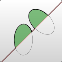
You can see from the picture that the different rotation parameters of the ellipse lead to different directions of the arcs drawn. Of course, this parameter has no effect on a perfect circle.
large-arc-flag and sweep-flag control the size and direction of the arc. Experience the difference of arcs in the following examples:
This HTML draws the following pictures:
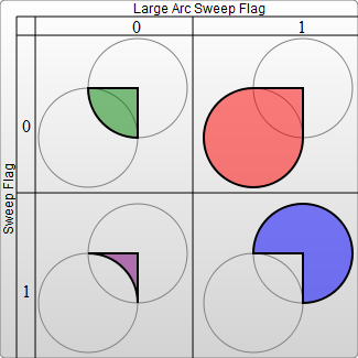
As can be seen from the above, these parameters are actually the only parameters needed to determine an arc. We also see here that the arcs in SVG are more complicated than those in canvas.
Instructions for drawing cubic Bezier curve: C x1 y1, x2 y2, x y
This HTML snippet draws the following graphic:
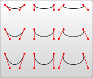
From the above we can see that the control points control the arc of the curve.
Special version of cubic Bezier curve: S x2 y2, x y
Many times, in order to draw a smooth curve, it is necessary to draw the curve multiple times continuously. At this time, in order to smooth the transition, the control point of the second curve is often the mapping point of the first curve control point on the other side of the curve. This simplified version can be used at this time. What should be noted here is that if there is no other S command or C command before the S command, the two control points will be considered to be the same at this time and degenerate into a quadratic Bezier curve; if the S command is used in another After the S command or the C command, the first control point of the subsequent S command will be set by default to a mapping point of the second control point of the previous curve. Try it out:
This HTML fragment draws the following graphics:
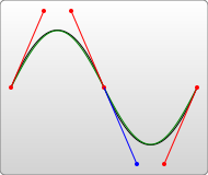
The S command above only has the second control point, and the first control point uses a mapping point of the second control point of the previous curve command.
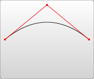
Instructions for drawing quadratic Bezier curve: Q x1 y1, x y, T x y (special version of quadratic Bezier curve)
Quadratic Bezier curve only A control point (x1, y1), usually as shown below:
If you are drawing a continuous curve, you can also use the simplified version T. Similarly, when T is preceded by a Q or T command, the control point of the subsequent T command will be set to the mapping point of the control point of the previous curve by default. Try it out:
This HTML fragment is drawn as follows Graphics:
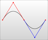
Similarly, if the T command is not preceded by a Q or T command, it is considered that there is no control point and a straight line is drawn.
The relative coordinate drawing instructions
have the same letters as the absolute coordinate drawing instructions, except that they are all lowercase. The parameters involving coordinates in the parameters of this set of instructions represent relative coordinates, which means that the parameters represent the offset from the current point to the target point. A positive number represents a positive offset to the axis, and a negative number represents a reverse offset. shift. However, for the Z command, there is no difference between upper and lower case.
It should be noted here that absolute coordinate instructions and relative coordinate instructions can be mixed . Sometimes mixing can lead to more flexible painting methods.
Notes on drawing SVG path:
When drawing graphics with holes, please note: the outer edges need to be drawn in counterclockwise order, and the inner edges of the holes The order must be clockwise. Only in this way will the filling effect of the graphics drawn be correct.
Practical reference:
Script index: http://msdn.microsoft.com/zh-cn/library/ff971910(v=vs.85).aspx
Development Center: https://developer.mozilla.org/en/SVG
Popular Reference: http://www.chinasvg.com/
Official documentation: http://www.w3.org/TR/SVG11/
Related articles
See more- AlloyTouch full-screen scrolling plug-in creates a smooth H5 page in 30 seconds
- HTML5 actual combat and analysis of touch events (touchstart, touchmove and touchend)
- Detailed explanation of image drawing examples in HTML5 canvas 9
- Regular expressions and new HTML5 elements
- How to combine NodeJS and HTML5 to drag and drop multiple files to upload to the server