Home >Technology peripherals >AI >Microsoft AR/VR patent proposes using angle and line features for multi-camera image alignment
Microsoft AR/VR patent proposes using angle and line features for multi-camera image alignment
- WBOYWBOYWBOYWBOYWBOYWBOYWBOYWBOYWBOYWBOYWBOYWBOYWBforward
- 2023-09-26 22:01:01935browse
MR systems can use multiple cameras, but they need to align the images when rendering them. However, image alignment is a challenging problem. Therefore, in a patent application titled "Method for Image Alignment Using Corner and Line Features", Microsoft proposed a solution
Of course, the industry already has methods of using corner features for image alignment. However, identifying corners in an image and aligning the image based on the identified corners is a time-consuming and computationally intensive operation.
What Microsoft proposes is a more effective improvement technology that can achieve better feature matching. The invention mainly introduces a hybrid method that uses corner features and line features to perform visual alignment, and this solution results in fewer constraints required in the alignment process, thereby improving computational efficiency and feature matching.
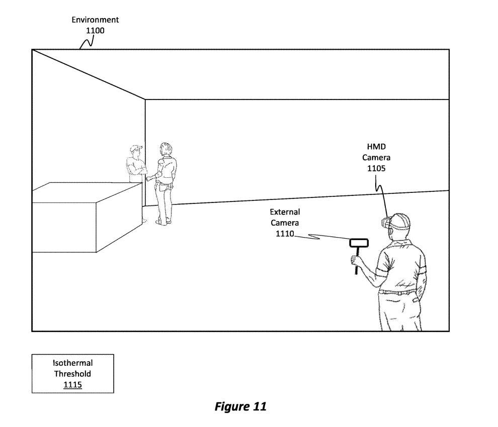
Figure 11 shows an example environment 1100 in which a user is using a head-mounted camera 1105 and an external camera 1110. As mentioned before, the image content generated from these two cameras needs to be aligned. But environment 1100 may be a low light environment, or it may be an environment that has low contrast in terms of thermal gradient or contrast.
For example, after the object cools down late at night, the temperature gradient of the environment may usually be uniform. In this case, the temperature profile or gradient of the environment may be below a specific isothermal threshold 1115 . In this case, traditional techniques for aligning content may fail. The embodiment described by Microsoft provides a solution for such scenarios.
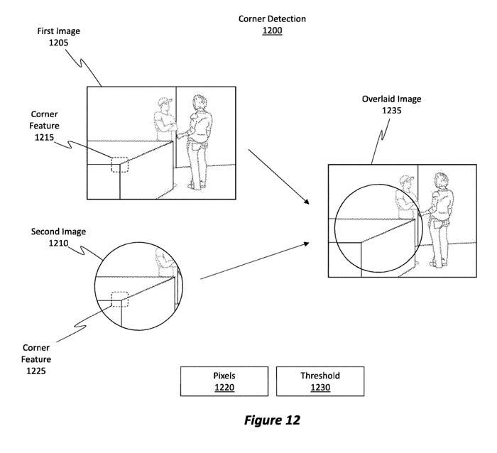
Figure 12 shows an example corner detection 1200 process that can be used to align images. Figure 12 shows a first image 1205 generated by the head-mounted camera 1105 of Figure 11, and a second image 1210 generated by the external camera 1110.
Perform corner detection operations to identify the "corners" present in the image. For example, embodiments may be used to identify corner features in the first image. In other words, a set of pixels can be identified in an image and determined to correspond to an angle.
"Corner" refers to one or more pixels of non-uniform intensity that has a first nearby block of pixels positioned horizontally relative to said one or more pixels and vertically positioned relative to said one or more pixels of the second nearby pixel block. In other words, a corner is defined as a set of one or more pixels that contrast with adjacent corners in the X and Y directions relative to the set of pixels.Identify the corner features 1215 in the first image 1205, and also identify the corner features in the second image 1210. Therefore, corner feature 1225 is successfully identified. It should be noted that angular feature 1225 and angular feature 1215 are corresponding
To align image content, this embodiment is tasked with identifying a threshold of 1230 corners. The threshold numbers of corners must correspond to each other. In other words, the multiple corners identified in the first image 1205 must be identified and must correspond to the multiple corners identified in the second image 1210
If these thresholds are met, embodiments may perform an image alignment operation to generate an overlay image 1235, an image in which content from the second image 1210 is aligned and then overlaid with corresponding content from the first image 1205 .
Performing corner detection and alignment is a computationally intensive operation, and if the match between the detected corners and the image is not good enough, the entire process may fail. For example, the method using only corner points requires identifying at least 5 corner points from one image and then matching them with the corresponding corner points in the second image. Under low contrast conditions, identifying even 5 corresponding corner points can be a challenge
After identifying a sufficient number of corners, embodiments then use the motion model to identify 3D rotations in order to adapt the image content from the first or second image by performing various rotations and transformations to align the 5 corners with each other. Another image. Performing such an alignment is computationally intensive.
Therefore, we need to reduce the constraints that exist when using only angular methods, and Figure 13 depicts such a technique.
Typically, it is easier to identify corresponding "lines" in an image than to identify corners, so the line detection process is usually faster than the corner detection process. Since the two processes can run in parallel and the line detection process is faster, adding the line detection process will not have a negative impact on the speed of the overall alignment process
By combining the use of lines to align images, fewer corners can be used during the alignment process, resulting in relaxed constraints and generally easier alignment. Especially in low temperature conditions, requiring the use of fewer corners is very beneficial because it is difficult to find and match corners
A "line" is defined as a set of one or more pixels that have a uniform intensity relative to a horizontally positioned first nearby pixel block of the set or sets of pixels, and have a uniform intensity relative to the set of one or more pixels. Uneven intensity of the vertically positioned second nearby pixel block of the pixel set. Alternatively, they have uneven intensity with respect to a horizontally positioned first nearby pixel block of one or more sets of pixels, and have uniform intensity with respect to a vertically positioned second nearby pixel block with respect to one or more sets of pixels.
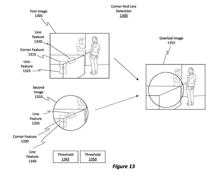
In Figure 13, a first image 1305 and a second image 1310 representative of the image in Figure 12 are shown. Figure 13 also shows an implementation method that can detect corner features 1315
in the first image 1305When detecting corner features on the first image 1305, line features are also detected at the same time, as shown in line features 1320 and 1325. Generally speaking, we can detect more lines
compared to the number of corners that can be detectedPerform angle and line operations on the second image 1310. For purposes of illustration, the embodiment identifies corner features 1330. In parallel with the corner detection operation, embodiments simultaneously detect lines in the second image 1310, such as line features 1335 and line features 1340.
Please note that corner feature 1330 corresponds to corner feature 1315; line feature 1335 corresponds to line feature 1320. Line feature 1340 corresponds to line feature 1325. Embodiments may identify these correspondences and then generate or use a motion model suitable for aligning these feature points with each other
According to the invention principle, we defined the first threshold as 1345. The first threshold refers to the number of corresponding angular features that must be identified in the two images in order to align them. At the same time, we also define a second threshold of 1350. The second threshold refers to the number of corresponding row features that must be identified in the two images in order for them to align
Satisfaction of first threshold 1345 and second threshold 1350 enables embodiments to align content from first image 1305 and second image 1310 to generate overlay image 1355. It is worth noting that the threshold usually refers to the total number of corners and lines that must be recognized.
After understanding the convenience and speed of performing line feature detection, you may question why embodiments only rely on line detection operations and avoid performing corner detection operations. The reason is because detecting lines in an image causes aperture issues.
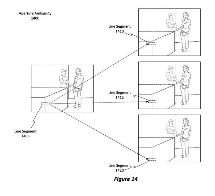
The following is the rewritten content: According to Figure 14, we can see the aperture problem, that is, the aperture ambiguity is 1400. In Figure 14, line segment 1405 is part of an entire line. Aperture ambiguity 1400 refers to the fact that multiple different parts of a line may (but incorrectly) relate to the identified line segment 1405
For example, line segment 1410 may be a block of pixels that matches line segment 1405, although line segment 1410 is actually in the wrong location or location. Similarly, line segment 1415 or line segment 1420 may contain blocks of pixels that may map or match pixels in line segment 1405. Such a scenario introduces ambiguity into the alignment process.
Therefore, relying on the line detection process itself is not enough technology. In other words, relying on combinations of lines and angles allows embodiments to use relaxed constraints, thereby improving computational efficiency.
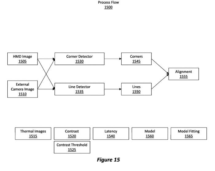
An example process flow 1500 is shown in Figure 15. Initially, a set of images is acquired, such as a head mounted camera image 1505 and an external camera image 1510. These images may be thermal images. The temperature gradient or contrast 1520 in the image may be below a certain contrast threshold 1525. Therefore, identifying a sufficient number of corners in an image can be quite difficult. In this case, a hybrid approach can be utilized to detect a combination of corners and lines to achieve alignment
Transmit the head-mounted camera image 1505 and the external camera image 1510 to the angle detector 1530 and the line detector 1535. These two detectors run simultaneously and have no dependency on each other
Please note that the line detector 1535 is generally faster at detecting lines than the corner detector 1530 at detecting angles. In other words, the delay time of the line detector 1535 is shorter than the delay time of the angle detector 1530
Corner detector 1530 analyzes the two images and identifies corner points 1545 in the images. Similarly, line detector 1535 analyzes the two images and identifies lines 1550 in the images. The embodiment then performs alignment 1555 by identifying corresponding corners and lines within the two images.
In order to perform alignment, a threshold number of lines and corners needs to be determined. The matching threshold is more relevant than the threshold for identifying the number of corners or lines. Embodiments then fit the identified corners and lines into a 3D model 1560 such as a motion model. Model fitting 1565 operations are then performed on the model 1560 to rotate, translate, and/or transform one image to match or align corresponding corners and lines in the other image.
In other words, when performing a reprojection operation, embodiments use identified corners and lines to align content from one image with content from another image
Related Patents: Microsoft Patent | Image alignment using corner and line features
The Microsoft patent application titled "Image alignment using corner and line features" was originally submitted in February 2022 and was recently published by the US Patent and Trademark Office.
The above is the detailed content of Microsoft AR/VR patent proposes using angle and line features for multi-camera image alignment. For more information, please follow other related articles on the PHP Chinese website!
Related articles
See more- AR/VR headset prompts and web app push notification support in iOS 15.4 beta
- As AR/VR product development continues, Apple adds a pair of mixed reality headset patents to its portfolio
- 4K+5000nit brightness? Apple Reality Pro headset AR/VR exposed
- Will AR/VR games usher in an ice-breaking journey? Apple releases first MR headset
- How to build AR/VR applications using PHP

