

 Technology peripheralsAIOne article to review the design of an ultra-comprehensive system time synchronization solution for the autonomous driving system
One article to review the design of an ultra-comprehensive system time synchronization solution for the autonomous driving system

The next generation autonomous driving system needs to use various sensors such as multiple laser radars, multiple millimeter wave radars, and multiple cameras. There is a delay from collecting data to processing and sending it to the domain controller, and there is a delay. The duration is unstable. In order to improve the performance of autonomous driving such as sensor fusion, decision planning and fusion positioning, the autonomous driving advanced domain controller HPC and its associated sensors need to be time synchronized. The actual process is to clearly define the timestamp information of the sensor input data (including the time). Stamping time and accuracy requirements), and also need to define the overall time synchronization plan and synchronization accuracy requirements.
1 Overview
To explain the principle of clock synchronization clearly, we need to first explain the two types of clock synchronization: data clock and management clock.
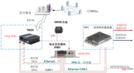
First of all, the UTC time provided by the combined inertial navigation system is used to provide timing to the time synchronization server through PPS GPRMC. The time synchronization server provides corresponding time information to various sensor data collection hosts through the PTP protocol and the central gateway. HPC needs to implement the time synchronization process between the internal SOC and MCU.
The data plane time between the HPC's SOC and MCU is synchronized through the gPTP protocol time, with the SOC as the master;
The management plane time between HPC's SOC and MCU is synchronized through the HPC private protocol. The SOC is the master and synchronized through the Ethernet link.
During the synchronization process between SOC and MCU, the management clock and data clock will be synchronized. The data plane uses the gPTP protocol. Within the time synchronization accuracy requirement of 250 microseconds, the management clock uses a private protocol. Also over Ethernet, the accuracy is 10ms. Its internal management time and data plane time need to be aligned. HPC must ensure the continuity of the data clock and does not allow abnormal jumps. Because abnormal jumps can cause serious data miscommunication and misinterpretation.
Every time the domain controller cold starts, the domain controller will try to communicate with the node that provides the master clock for a certain period of time (this time can be calibrated as needed according to the actual situation) to Perform initial synchronization. If the synchronization is successful, the data clock will use the current management time to synchronize the obtained absolute time; the corresponding driver can be started with it and call the corresponding application software for calculation. If synchronization is unsuccessful, the domain controller will keep trying to synchronize.
2 Synchronization process between HPC and VDC
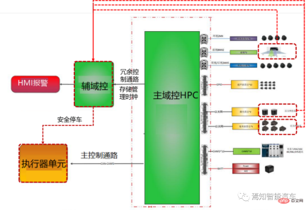
The entire synchronization classification mainly includes central domain controllers and gateways, various sensors and actuators synchronization between. The absolute time of HPC usually provides a unified time source for all controllers of the vehicle through the central gateway CGW, and outputs the overall synchronization timestamp to all associated controllers (such as body domain controller PDC, vehicle domain controller VDC, cockpit Domain Controller CSC, etc.). In the next-generation autonomous driving system architecture, the vehicle domain controller VDC not only assumes the function of controlling the operation of the vehicle actuator, but also serves as the central gateway CGW, carrying information interaction and protocols between HPC and other domain controllers. Transformation function.
The following figure shows the connection relationship between the automatic driving controller HPC and its associated domain controller.
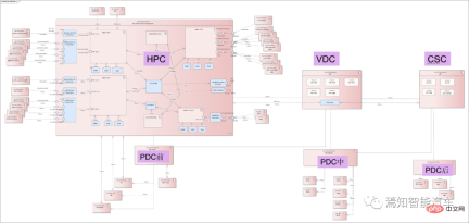
As mentioned above, VDC can function as a central gateway, so the HPC-centered inter-controller synchronization process focuses on the relationship between HPC and VDC. Synchronization process. Synchronization and communication functions between domain controllers can be realized through VDC information transfer. Each controller is mainly directly connected through Ethernet, using the Ethernet-based gPTP protocol. The synchronization process between HPC and VDC needs to consider the absolute time of the GNSS input directly connected to the HPC as the main clock, and the time error is relatively small (usually within 10ms). Considering the accuracy of smart driving big data cloud analysis, and the gPTP protocol accuracy is usually required to be within 250 microseconds, the HPC and VDC fixed periods can be synchronized using integer multiples of the accuracy (such as 125 milliseconds).
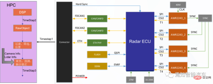
3 Synchronization process of HPC local network node
The synchronization process of HPC local network node refers to the synchronization process between it and the sensor. In the autonomous driving private internal network, the domain controller is used as the master node, and its corresponding data end time is used as the time source. HPC provides a unified time source to sensors (lidar, millimeter-wave radar, driving camera, surround-view camera, combined inertial navigation, etc.) through the local intranet. During the process, lidar and combined inertial navigation are connected via Ethernet (1PPS reserved), millimeter wave radar and ultrasonic box PDC are connected via CANFD/Ethernet, and cameras (including driving/surround view cameras) are connected via GSML/LVDS. This type of different network connection forms are used as slave nodes for time synchronization with the gateway.
It mainly includes three major sensors as follows:
Visual sensor
Distinguish between driving control and parking control cameras.
Driving cameras mainly include front-view cameras, side-view cameras, and rear-view cameras. Parking cameras mainly refer to surround-view cameras; the cameras after adopting a centralized solution are usually no longer integrated It is a machine, but a simple sensor, and the input is the original image.
HPC and camera transmit data through video data cables such as GSML or LVDS. HPC uses its data clock (i.e. system time, not absolute time) as the time source to send trigger signals regularly. Trigger Signal is given to the camera, and the camera adjusts the exposure time based on the real-time trigger signal. Since the corresponding timestamp cannot be directly recorded in a single camera, multi-camera synchronization triggering is used for synchronization, and the moment when the trigger signal in the domain controller is recorded is used as the initial timestamp of the image.
The camera is time-stamped at all times during the imaging process (calculated as follows), and the time accuracy is required to be within 10ms.
Tmidtime imaging middle=Ttrigger (trigger time) 1/2*Texposure (exposure time);
The exposure time in the above formula is fixed of.
Since the trigger moment is at the end of the exposure of the entire frame image, in order to improve the accuracy of the timestamp, the exposure duration needs to be compensated to obtain the exposure end point time of the middle row to represent the entire frame image The middle moment of exposure; usually the following formula is used for time compensation.
Tcompensate (compensation time) = length of each line × total number of lines/2
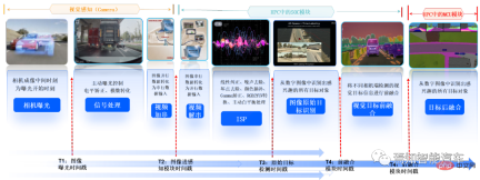
The domain controller recording time includes the following 5 times: The intermediate time of camera imaging, the time when the image enters the perception module, the time when the image perception result enters the fusion module, the time when the perception fusion result is sent, and the time when the downstream module receives it.
##Lidar
Currently, semi-solid laser radar is mainly used.
HPC and lidar are usually based on the Ethernet gPTP protocol combined with Gigabit Ethernet direct connection. HPC is the master node Master, and lidar is the slave node Slave. The HPC synchronization time source uses absolute time (i.e. system time) as the data clock, and the time synchronization accuracy requirement is still within 250 microseconds. HPC and lidar use an integer multiple of the synchronization time accuracy (for example, it can be 125 milliseconds or 250ms) for synchronization. The lidar needs to update the time in real time according to this synchronization process. In addition, lidar needs to emit the time of each point in each frame of point cloud as the time requirement for sensor timestamp (accuracy requirement is within 1ms).
Similarly, the domain controller needs to record the time of the laser point cloud sending point based on the lidar return time (that is, the moment when the lidar can record each point when receiving the reflected signal); enter the domain controller timestamp (Usually the lidar already has corresponding time information at this time, and HPC does not need to stamp the timestamp); Laser sensing module timestamp (generally, the lidar supplier will process the original point cloud information. If it is a centralized solution, it will be processed by The SOC in HPC is responsible for front-end point cloud sensing, and the proprietary SOC performs sensing and back-end fusion); the sensing results are sent with a timestamp to the downstream module for reception; and the last timestamp needs to be stamped at this time. For laser point cloud sensing, the data clock of the domain controller is mainly used for sensing algorithm design (such algorithms can be on the car or on the cloud), while the absolute time mainly involves local time and is mainly used for data recording and storage services. .
Millimeter wave radar
Mainly refers to front millimeter wave radar and angular millimeter wave radar.
Usually the front millimeter wave radar synchronizes information alone, while the angular millimeter wave radar group itself will have a main radar to further synchronize all its information. Generally speaking, for the previous generation of autonomous driving, millimeter wave radar input data usually uses target-level data. However, after the next generation domain controller adopts a centralized solution, when upgrading 3D millimeter wave radar to 4D millimeter wave radar, it will be processed directly. The call for millimeter-wave radar point clouds is getting louder and louder. In this process, the millimeter-wave radar no longer has a computing unit, but simply inputs point cloud data.
However, because millimeter wave radar microwave signal processing is still very difficult, for the next generation of autonomous driving systems, many OEMs still use target-level data for direct connection and time synchronization. The accuracy requirements are usually broader than lidar, usually within 1ms. The time between when the point cloud millimeter wave radar sends out and when it receives the echo is marked as a timestamp, and the accuracy is required to be within 1ms.
At the same time, HPC and millimeter wave radar are synchronized by setting a period interval of 1-2 seconds. During this time period, the millimeter wave radar updates the corresponding time in real time. Similarly, the domain controller supports recording timestamps containing the following five moments based on the millimeter wave radar return time:
Echo reflection point generation timestamp, echo input to the domain controller Timestamp (of course, for target-level data records, its millimeter-wave radar already carries timestamp information, and Huawei no longer timestamps it); the target information output by the millimeter-wave radar is filtered by original reflection point clustering, in order to obtain more accurate timestamp, usually it is necessary to obtain the timestamp of the time when the original reflection point was generated, as shown in the red part in the figure below.
The sensing results are sent to a dedicated SOC/MCU and fused with other sensors with timestamps. Similarly, the domain controller's data time (or local time) is used for algorithm design operations, while absolute time is used for data recording and storage operations.
HPC needs to add a timestamp corresponding to the entry moment of the smart camera and radar packets, and timestamp the data into the sensing module as a backup for use with millimeter wave Radar confirmation, especially angle radar, requires time synchronization information to determine whether the angle radar can launch the target.
Combined inertial navigation/independent inertial navigation system
In the next generation of autonomous driving systems , Different OEMs have different types of inertial navigation, which are usually divided into two types: combined inertial navigation and independent inertial navigation according to their self-research capabilities. Since the combined inertial navigation has a built-in satellite-inertial combination algorithm, based on the actual application situation, here we only explain the direct connection of the simpler combined inertial navigation. HPC serves as the master node Master and the combined inertial navigation system serves as the slave node. It is directly connected to the combined inertial navigation system through 100M Ethernet.
Among them, Ethernet is still based on the gPTP protocol. The HPC synchronization time source still uses the data clock (i.e. system time, not absolute time) for synchronization. Required time synchronization accuracy requirements: within 250 microseconds, the synchronization period is an integer multiple of the synchronization accuracy requirements (such as 1 millisecond or 125 milliseconds). During this period, the combined inertial navigation timestamps the latest IMU sampling based on RTK and IMU information. Its accuracy is limited to 1ms.
In addition, the sampling time of the IMU, the time of entering the HPC, and the time of entering the back-end fusion module will all be timestamped.
4 Time synchronization process of HPC external network nodes
In addition to internal network node time synchronization, for the next generation autonomous driving system , there is a large amount of external information interaction between it and the associated actuators (such as the integrated brake control system EPBi, the electronic steering system EPS, and the power control system VCU). Referring to the phased centralized control method, this type of vehicle control port is usually connected and synchronously controlled through the vehicle controller VDC. As mentioned above, the VDC can actually be regarded as a central gateway. In addition to forwarding information to various domain controllers, it is also responsible for the definition and sending of the entire synchronization timestamp. Because for the entire vehicle system, the entire absolute time is obtained from the GNSS/GPS connected to the domain controller HPC of the autonomous driving system.
The associated system usually performs independent time synchronization control through the vehicle domain control port (VDC), so there is usually no direct master-slave connection between HPC and ESP, EPS, and VCU. For this type of time synchronization relationship between nodes, the respective timestamps are directly sent to the VDC controller during the execution of instructions, and time alignment is performed during the execution.
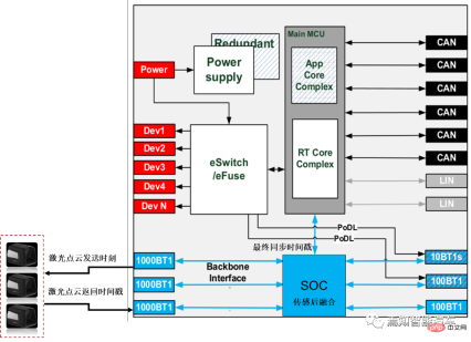
5 The time synchronization process in the HPC safety redundancy control process
For the entire autonomous driving system, the time synchronization process is still Corresponding failure control logic needs to be considered. Taking into account the different functions carried by the AI chip SOC and logic chip MCU contained in it. There is usually some degree of functional degradation at different times when both fail. This type of functional degradation is called partial functional degradation. During partial function degradation, if part of the SOC fails, the MCU synchronizes with the sensor through the crystal oscillator maintenance time. During this period, the camera target data information passed by Radar and other SOCs can still be received, and the output timestamp remains stable. Therefore, it can be said that after partial function downgrade, the system will still use the original timestamp for response in a short period of time, and the MCU can still maintain the stability of the original time data (the time synchronization process can be carried out with reference to the internal clock in the MCU), supporting the operation of the function. Because the error is very small in a short period of time, the risk of not synchronizing time within this period is also very small.
Of course, if the entire HPC fails, another backup controller is needed (it can be another low-profile version of HPC, or it can be an additional Added smart camera (Smart Camera) for security control. During this process, the time synchronization relationship between the backup controller and the corresponding sensor needs to be re-established.
Another failure mode is functional degradation caused by power failure. It should be noted here that there are two sleep modes for domain controllers: deep sleep and light sleep. This sleep mode is mainly related to whether to cut off the overall power supply. If the controller is in deep sleep, the data clock directly uses the management clock stored at the last power-off without re-timing. If the controller is in light sleep, the management clock of this power-off is directly used for timing. Compared with deep sleep, the clock results of light sleep synchronization are more accurate. Of course, no matter how deep or light the sleep is, the controller clock is always invalid during this period, and all software cannot run normally. Of course, the entire conversion time from light sleep to deep sleep can be customized (such as 12 hours).
6 Summary
This article explains in detail the time synchronization principle of each control unit of the next-generation autonomous driving system, and explains the synchronization process Each module puts forward accuracy requirements, involving local network node synchronization and global network node synchronization. Among them, local network node synchronization is mainly aimed at the synchronization relationship between the sensors and domain control inside the autonomous driving system. Global network node synchronization is mainly aimed at the time synchronization relationship between the autonomous driving system and external related systems (such as controlling braking, steering, power, doors, lights, gateways, etc.).
For the overall calculation accuracy, local network node synchronization is crucial, because there are many sensor units involved, and each needs to have a corresponding timestamp based on its actual situation, and finally the domain controller will perform the summary. Synchronize. For global network node synchronization, time information can be simply exchanged by referring to the information interaction between each sub-domain controller and the HPC. It should be noted here that the absolute time of the entire system comes from the GNSS system, which can usually be connected and input by HPC or CSC.
The above is the detailed content of One article to review the design of an ultra-comprehensive system time synchronization solution for the autonomous driving system. For more information, please follow other related articles on the PHP Chinese website!

 Meta's New AI Assistant: Productivity Booster Or Time Sink?May 01, 2025 am 11:18 AM
Meta has joined hands with partners such as Nvidia, IBM and Dell to expand the enterprise-level deployment integration of Llama Stack. In terms of security, Meta has launched new tools such as Llama Guard 4, LlamaFirewall and CyberSecEval 4, and launched the Llama Defenders program to enhance AI security. In addition, Meta has distributed $1.5 million in Llama Impact Grants to 10 global institutions, including startups working to improve public services, health care and education. The new Meta AI application powered by Llama 4, conceived as Meta AI
 80% Of Gen Zers Would Marry An AI: StudyMay 01, 2025 am 11:17 AM
Joi AI, a company pioneering human-AI interaction, has introduced the term "AI-lationships" to describe these evolving relationships. Jaime Bronstein, a relationship therapist at Joi AI, clarifies that these aren't meant to replace human c
 AI Is Making The Internet's Bot Problem Worse. This $2 Billion Startup Is On The Front LinesMay 01, 2025 am 11:16 AM
Online fraud and bot attacks pose a significant challenge for businesses. Retailers fight bots hoarding products, banks battle account takeovers, and social media platforms struggle with impersonators. The rise of AI exacerbates this problem, rende
 Selling To Robots: The Marketing Revolution That Will Make Or Break Your BusinessMay 01, 2025 am 11:15 AM
AI agents are poised to revolutionize marketing, potentially surpassing the impact of previous technological shifts. These agents, representing a significant advancement in generative AI, not only process information like ChatGPT but also take actio
 How Computer Vision Technology Is Transforming NBA Playoff OfficiatingMay 01, 2025 am 11:14 AM
AI's Impact on Crucial NBA Game 4 Decisions Two pivotal Game 4 NBA matchups showcased the game-changing role of AI in officiating. In the first, Denver's Nikola Jokic's missed three-pointer led to a last-second alley-oop by Aaron Gordon. Sony's Haw
 How AI Is Accelerating The Future Of Regenerative MedicineMay 01, 2025 am 11:13 AM
Traditionally, expanding regenerative medicine expertise globally demanded extensive travel, hands-on training, and years of mentorship. Now, AI is transforming this landscape, overcoming geographical limitations and accelerating progress through en
 Key Takeaways From Intel Foundry Direct Connect 2025May 01, 2025 am 11:12 AM
Intel is working to return its manufacturing process to the leading position, while trying to attract fab semiconductor customers to make chips at its fabs. To this end, Intel must build more trust in the industry, not only to prove the competitiveness of its processes, but also to demonstrate that partners can manufacture chips in a familiar and mature workflow, consistent and highly reliable manner. Everything I hear today makes me believe Intel is moving towards this goal. The keynote speech of the new CEO Tan Libo kicked off the day. Tan Libai is straightforward and concise. He outlines several challenges in Intel’s foundry services and the measures companies have taken to address these challenges and plan a successful route for Intel’s foundry services in the future. Tan Libai talked about the process of Intel's OEM service being implemented to make customers more
 AI Gone Wrong? Now There's Insurance For ThatMay 01, 2025 am 11:11 AM
Addressing the growing concerns surrounding AI risks, Chaucer Group, a global specialty reinsurance firm, and Armilla AI have joined forces to introduce a novel third-party liability (TPL) insurance product. This policy safeguards businesses against


Hot AI Tools

Undresser.AI Undress
AI-powered app for creating realistic nude photos

AI Clothes Remover
Online AI tool for removing clothes from photos.

Undress AI Tool
Undress images for free

Clothoff.io
AI clothes remover

Video Face Swap
Swap faces in any video effortlessly with our completely free AI face swap tool!

Hot Article
Hot Tools

VSCode Windows 64-bit Download
A free and powerful IDE editor launched by Microsoft

DVWA
Damn Vulnerable Web App (DVWA) is a PHP/MySQL web application that is very vulnerable. Its main goals are to be an aid for security professionals to test their skills and tools in a legal environment, to help web developers better understand the process of securing web applications, and to help teachers/students teach/learn in a classroom environment Web application security. The goal of DVWA is to practice some of the most common web vulnerabilities through a simple and straightforward interface, with varying degrees of difficulty. Please note that this software

Atom editor mac version download
The most popular open source editor

Notepad++7.3.1
Easy-to-use and free code editor

SublimeText3 English version
Recommended: Win version, supports code prompts!

