
Home >Web Front-end >H5 Tutorial >Detailed explanation of graphic and text code for 3D network topology tree presentation based on HTML5
Detailed explanation of graphic and text code for 3D network topology tree presentation based on HTML5

- 黄舟Original
- 2017-03-07 15:36:481970browse
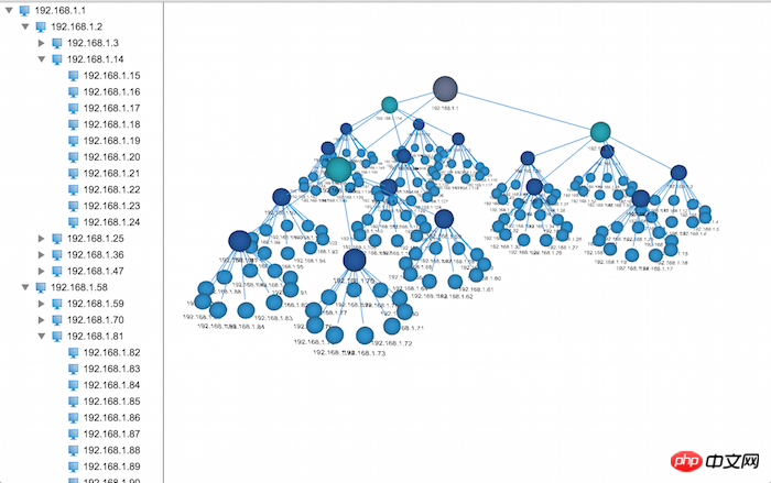
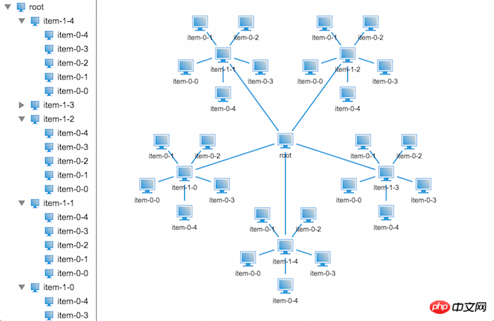
In HT for Web, both 2D and 3D applications support the display of tree structure data, with different display effects. The tree structure on 2D has an obvious hierarchical relationship, but if the amount of data is large, , it seems not so intuitive, and it is more difficult to find the specified node. However, the tree structure in 3D will appear more intuitive when combined with the elastic layout component of HT for Web. You can see the entire tree structure data at a glance. A rough idea, but under the influence of elastic layout, the hierarchical structure is not so clear. So at this time, the need for a 3D tree with a clear structure comes. So what exactly does this 3D tree look like? Let’s see it together~
To achieve this Effect, where to start? Next, we will break this problem down into several small problems to solve.
1. Create a tree structure
Those who have learned about HT for Web should be familiar with the creation of tree structure data, so I will not discuss it in depth here. . The creation of tree structure data is very simple. In order to make the code more concise, I have encapsulated three methods to create tree structure data. The specific code is as follows:
/**
 * 创建连线
 * @param {ht.DataModel} dataModel - 数据容器
 * @param {ht.Node} source - 起点
 * @param {ht.Node} target - 终点
 */
function createEdge(dataModel, source, target) {
    // 创建连线,链接父亲节点及孩子节点
    var edge = new ht.Edge();
    edge.setSource(source);
    edge.setTarget(target);
    dataModel.add(edge);
}

/**
 * 创建节点对象
 * @param {ht.DataModel} dataModel - 数据容器
 * @param {ht.Node} [parent] - 父亲节点
 * @returns {ht.Node} 节点对象
 */
function createNode(dataModel, parent) {
    var node = new ht.Node();
    if (parent) {
        // 设置父亲节点
        node.setParent(parent);

        createEdge(dataModel, parent, node);
    }
    // 添加到数据容器中
    dataModel.add(node);
    return node;
}

/**
 * 创建结构树
 * @param {ht.DataModel} dataModel - 数据容器
 * @param {ht.Node} parent - 父亲节点
 * @param {Number} level - 深度
 * @param {Array} count - 每层节点个数
 * @param {function(ht.Node, Number, Number)} callback - 回调函数(节点对象,节点对应的层级,节点在层级中的编号)
 */
function createTreeNodes(dataModel, parent, level, count, callback) {
    level--;
    var num = (typeof count === 'number' ? count : count[level]);

    while (num--) {
        var node = createNode(dataModel, parent);
        // 调用回调函数,用户可以在回调里面设置节点相关属性
        callback(node, level, num);
        if (level === 0) continue;
        // 递归调用创建孩子节点
        createTreeNodes(dataModel, node, level, count, callback);
    }
}
Hehe, the code may be a bit complicated to write. , the simple way is to nest several for loops to create tree-structured data. I won’t go into details here. Next, let’s explore the second question.
2. Simulate the radius calculation of each layer of the 3D tree structure under 2D topology
The biggest problem with the tree structure under 3D is that the level of each node and the level of each layer A node's radius is calculated around its parent node. Now that the tree structure data is available, it is time to start calculating the radius. We start from the two-layer tree structure:

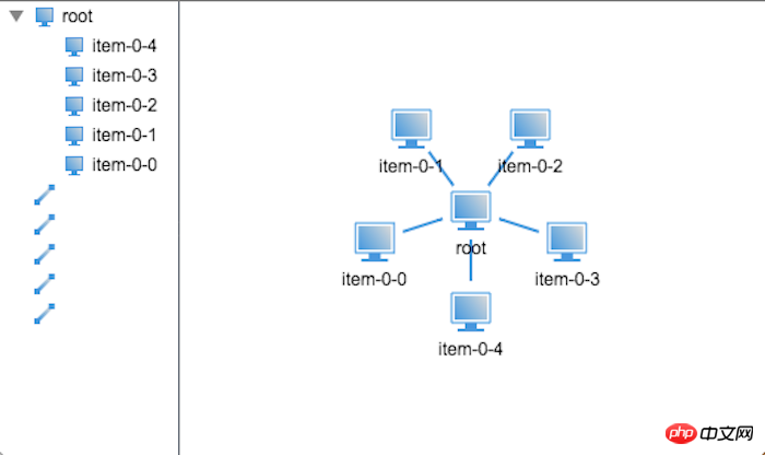
I now create two In the layered tree structure, all child nodes are lined up and do not surround their parent nodes. So how do we determine the positions of these child nodes?
First of all, we need to know that each end node has a circle of its own domain, otherwise there will be overlap between nodes, so here, we assume that the domain radius of the end node is 25, Then the shortest distance between two adjacent nodes will be twice the node field radius, which is 50, and these end nodes will evenly surround their parent nodes, then the opening angle of the two adjacent nodes can be confirmed Come out, with the opening angle and the distance between two points, the shortest radius of a node around its parent node can also be calculated. Suppose the opening angle is a and the minimum distance between two points is b, then the minimum radius r The calculation formula is:
r = b / 2 / sin(a / 2);
Then let’s lay out the tree. The code is written like this:
/**
 * 布局树
 * @param {ht.Node} root - 根节点
 * @param {Number} [minR] - 末端节点的最小半径
 */
function layout(root, minR) {
    // 设置默认半径
    minR = (minR == null ? 25 : minR);
    // 获取到所有的孩子节点对象数组
    var children = root.getChildren().toArray();
    // 获取孩子节点个数
    var len = children.length;
    // 计算张角
    var degree = Math.PI * 2 / len;
    // 根据三角函数计算绕父亲节点的半径
    var sin = Math.sin(degree / 2),
        r = minR / sin;
    // 获取父亲节点的位置坐标
    var rootPosition = root.p();

    children.forEach(function(child, index) {
        // 根据三角函数计算每个节点相对于父亲节点的偏移量
        var s = Math.sin(degree * index),
            c = Math.cos(degree * index),
            x = s * r,
            y = c * r;

        // 设置孩子节点的位置坐标
        child.p(x + rootPosition.x, y + rootPosition.y);
    });
}
In the code, you will find that I set the end radius to 25 by default. In this way, we can lay out the structure tree by calling the layout() method. The layout effect is as follows:

It can be seen from the renderings that the default radius of the end node is not very ideal. The layout effect is almost invisible, so we can increase the default radius of the end node to solve the problem. The problem of too dense layout, for example, the effect of setting the default radius to 40 is as follows:
Now that the two-layer tree distribution is solved, let’s take a look at the three-layer How to deal with the tree distribution.
Considering the second layer and the third layer as a whole, the tree structure of the three layers is actually the same as the two layers. The difference is that when processing the second layer nodes, they should be regarded as To process a two-layer tree structure, it is best to use recursion to process this kind of regularity, so we will slightly modify the code and see how it works:
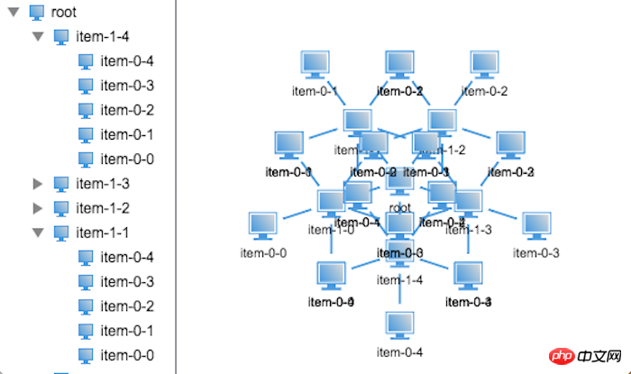
No, the nodes are all overlapping. It seems that simple recursion will not work. So where is the specific problem?
After careful analysis, I found that the domain radius of the father node is determined by the domain radius of its child node. Therefore, you need to know the domain radius of your own node during layout, and the position of the node depends on the domain of the father node. Radius and position information, so that the node position cannot be laid out while calculating the radius.
Now we can only separate the calculation of the radius from the layout and do a two-step operation. Let’s first analyze the calculation of the node radius:
First we need to clarify the most critical conditions, father The radius of a node depends on the radius of its child node. This condition tells us that the node radius can only be calculated from bottom to top. Therefore, the recursive function we design must be recursive first and then calculated. Without further ado, let’s take a look at the specifics. Code:
/**
 * 就按节点领域半径
 * @param {ht.Node} root - 根节点对象
 * @param {Number} minR - 最小半径
 */
function countRadius(root, minR) {
    minR = (minR == null ? 25 : minR);

    // 若果是末端节点,则设置其半径为最小半径
    if (!root.hasChildren()) {
        root.a('radius', minR);
        return;
    }

    // 遍历孩子节点递归计算半径
    var children = root.getChildren();
    children.each(function(child) {
        countRadius(child, minR);
    });

    var child0 = root.getChildAt(0);
    // 获取孩子节点半径
    var radius = child0.a('radius');

    // 计算子节点的1/2张角
    var degree = Math.PI / children.size();
    // 计算父亲节点的半径
    var pRadius = radius / Math.sin(degree);

    // 设置父亲节点的半径及其孩子节点的布局张角
    root.a('radius', pRadius);
    root.a('degree', degree * 2);
}
OK,半径的计算解决了,那么接下来就该解决布局问题了,布局树状结构数据需要明确:孩子节点的坐标位置取决于其父亲节点的坐标位置,因此布局的递归方式和计算半径的递归方式不同,我们需要先布局父亲节点再递归布局孩子节点,具体看看代码吧:
/**
 * 布局树
 * @param {ht.Node} root - 根节点
 */
function layout(root) {
    // 获取到所有的孩子节点对象数组
    var children = root.getChildren().toArray();
    // 获取孩子节点个数
    var len = children.length;
    // 计算张角
    var degree = root.a('degree');
    // 根据三角函数计算绕父亲节点的半径
    var r = root.a('radius');
    // 获取父亲节点的位置坐标
    var rootPosition = root.p();

    children.forEach(function(child, index) {
        // 根据三角函数计算每个节点相对于父亲节点的偏移量
        var s = Math.sin(degree * index),
            c = Math.cos(degree * index),
            x = s * r,
            y = c * r;

        // 设置孩子节点的位置坐标
        child.p(x + rootPosition.x, y + rootPosition.y);

        // 递归调用布局孩子节点
        layout(child);
    });
}
代码写完了,接下来就是见证奇迹的时刻了,我们来看看效果图吧:
不对呀,代码应该是没问题的呀,为什么显示出来的效果还是会重叠呢?不过仔细观察我们可以发现相比上个版本的布局会好很多,至少这次只是末端节点重叠了,那么问题出在哪里呢?
不知道大家有没有发现,排除节点自身的大小,倒数第二层节点与节点之间的领域是相切的,那么也就是说节点的半径不仅和其孩子节点的半径有关,还与其孙子节点的半径有关,那我们把计算节点半径的方法改造下,将孙子节点的半径也考虑进去再看看效果如何,改造后的代码如下:
/**
 * 就按节点领域半径
 * @param {ht.Node} root - 根节点对象
 * @param {Number} minR - 最小半径
 */
function countRadius(root, minR) {
   ……

    var child0 = root.getChildAt(0);
    // 获取孩子节点半径
    var radius = child0.a('radius');

    var child00 = child0.getChildAt(0);
    // 半径加上孙子节点半径,避免节点重叠
    if (child00) radius += child00.a('radius');

   ……
}
下面就来看看效果吧~
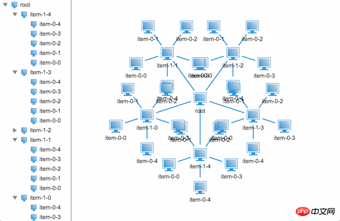
哈哈,看来我们分析对了,果然就不再重叠了,那我们来看看再多一层节点会是怎么样的壮观场景呢?

哦,NO!这不是我想看到的效果,又重叠了,好讨厌。
不要着急,我们再来仔细分析分析下,在前面,我们提到过一个名词——领域半径,什么是领域半径呢?很简单,就是可以容纳下自身及其所有孩子节点的最小半径,那么问题就来了,末端节点的领域半径为我们指定的最小半径,那么倒数第二层的领域半径是多少呢?并不是我们前面计算出来的半径,而应该加上末端节点自身的领域半径,因为它们之间存在着包含关系,子节点的领域必须包含于其父亲节点的领域中,那我们在看看上图,是不是感觉末端节点的领域被侵占了。那么我们前面计算出来的半径代表着什么呢?前面计算出来的半径其实代表着孩子节点的布局半径,在布局的时候是通过该半径来布局的。
OK,那我们来总结下,节点的领域半径是其下每层节点的布局半径之和,而布局半径需要根据其孩子节点个数及其领域半径共同决定。
好了,我们现在知道问题的所在了,那么我们的代码该如何去实现呢?接着往下看:
/**
 * 就按节点领域半径及布局半径
 * @param {ht.Node} root - 根节点对象
 * @param {Number} minR - 最小半径
 */
function countRadius(root, minR) {
    minR = (minR == null ? 25 : minR);

    // 若果是末端节点,则设置其布局半径及领域半径为最小半径
    if (!root.hasChildren()) {
        root.a('radius', minR);
        root.a('totalRadius', minR);
        return;
    }

    // 遍历孩子节点递归计算半径
    var children = root.getChildren();
    children.each(function(child) {
        countRadius(child, minR);
    });

    var child0 = root.getChildAt(0);
    // 获取孩子节点半径
    var radius = child0.a('radius'),
        totalRadius = child0.a('totalRadius');

    // 计算子节点的1/2张角
    var degree = Math.PI / children.size();
    // 计算父亲节点的布局半径
    var pRadius = totalRadius / Math.sin(degree);

    // 缓存父亲节点的布局半径
    root.a('radius', pRadius);
    // 缓存父亲节点的领域半径
    root.a('totalRadius', pRadius + totalRadius);
    // 缓存其孩子节点的布局张角
    root.a('degree', degree * 2);
}
在代码中我们将节点的领域半径缓存起来,从下往上一层一层地叠加上去。接下来我们一起验证其正确性:
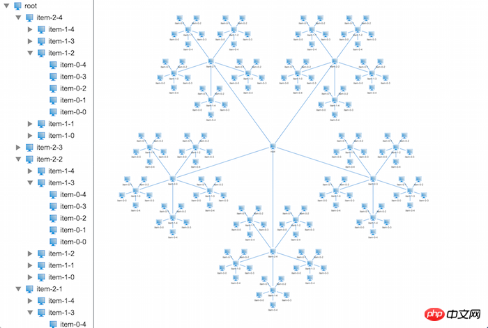
搞定,就是这样子了,2D拓扑上面的布局搞定了,那么接下来该出动3D拓扑啦~
3. 加入z轴坐标,呈现3D下的树状结构
3D拓扑上面布局无非就是多加了一个坐标系,而且这个坐标系只是控制节点的高度而已,并不会影响到节点之间的重叠,所以接下来我们来改造下我们的程序,让其能够在3D上正常布局。
也不需要太大的改造,我们只需要修改下布局器并且将2D拓扑组件改成3D拓扑组件就可以了。
/**
* 布局树
* @param {ht.Node} root - 根节点
*/
function layout(root) {
// 获取到所有的孩子节点对象数组
var children = root.getChildren().toArray();
// 获取孩子节点个数
var len = children.length;
// 计算张角
var degree = root.a('degree');
// 根据三角函数计算绕父亲节点的半径
var r = root.a('radius');
// 获取父亲节点的位置坐标
var rootPosition = root.p3();
children.forEach(function(child, index) {
// 根据三角函数计算每个节点相对于父亲节点的偏移量
var s = Math.sin(degree * index),
c = Math.cos(degree * index),
x = s * r,
z = c * r;
// 设置孩子节点的位置坐标
child.p3(x + rootPosition[0], rootPosition[1] - 100, z + rootPosition[2]);
// 递归调用布局孩子节点
layout(child);
});
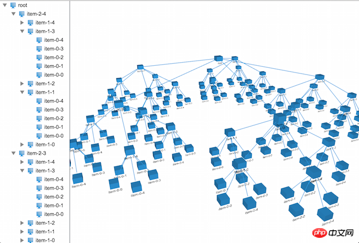
}上面是改造成3D布局后的布局器代码,你会发现和2D的布局器代码就差一个坐标系的的计算,其他的都一样,看下在3D上布局的效果:
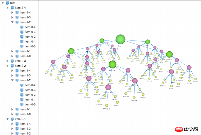
恩,有模有样的了,在文章的开头,我们可以看到每一层的节点都有不同的颜色及大小,这些都是比较简单,在这里我就不做深入的讲解,具体的代码实现如下:
var level = 4,
    size = (level + 1) * 20;

var root = createNode(dataModel);
root.setName('root');
root.p(100, 100);

root.s('shape3d', 'sphere');
root.s('shape3d.color', randomColor());
root.s3(size, size, size);

var colors = {},
    sizes = {};
createTreeNodes(dataModel, root, level - 1, 5, function(data, level, num) {
    if (!colors[level]) {
        colors[level] = randomColor();
        sizes[level] = (level + 1) * 20;
    }

    size = sizes[level];

    data.setName('item-' + level + '-' + num);
    // 设置节点形状为球形
    data.s('shape3d', 'sphere');
    data.s('shape3d.color', colors[level]);
    data.s3(size, size, size);
});
在这里引入了一个随机生成颜色值的方法,对每一层随机生成一种颜色,并将节点的形状改成了球形,让页面看起来美观些(其实很丑)。
提个外话,节点上可以贴上图片,还可以设置文字的朝向,可以根据用户的视角动态调整位置,等等一系列的拓展,这些大家都可以去尝试,相信都可以做出一个很漂亮的3D树出来。
到此,整个Demo的制作就结束了,今天的篇幅有些长,感谢大家的耐心阅读,在设计上或则是表达上有什么建议或意见欢迎大家提出,点击这里可以访问HT for Web官网上的手册。
The above is the detailed explanation of the graphic code of the 3D network topology tree based on HTML5. For more related content, please pay attention to the PHP Chinese website (www.php.cn)!
Related articles
See more- AlloyTouch full-screen scrolling plug-in creates a smooth H5 page in 30 seconds
- HTML5 actual combat and analysis of touch events (touchstart, touchmove and touchend)
- Detailed explanation of image drawing examples in HTML5 canvas 9
- Regular expressions and new HTML5 elements
- How to combine NodeJS and HTML5 to drag and drop multiple files to upload to the server