


php Xiaobian Yuzai will introduce to you how to connect the chassis cable to the motherboard. The chassis cable is an important component that connects the power supply, USB interface, audio interface and other devices inside the chassis to the motherboard. There are many ways to connect the chassis cable to the motherboard. The most common way is to connect the pin header on the motherboard to the pins of the chassis cable. Pins come in different shapes and numbers and need to be matched according to the interface type of the motherboard and chassis. When connecting the pins, pay attention to the direction and position, and ensure that the pins and sockets correspond correctly to avoid connection errors or damage to the equipment. At the same time, you also need to pay attention to the arrangement and fixation of cables to ensure a stable and reliable connection. By correctly connecting the chassis cable to the motherboard, various devices can work normally and improve the performance and user experience of the computer.

How to connect the chassis cable to the motherboard?
How to connect the motherboard and the chassis:
First plug the USB3.0 into the motherboard USB3.0 interface. Don’t worry, it has a fool-proof design. If it is plugged in backwards, it will not go in.
Then plug in the front USB interface and front audio interface. These interfaces are also designed to be fool-proof, so if you make a mistake, you cannot insert them. First plug in the USB interface. The interface marked by USB corresponds to the one on the motherboard. on the USB logo interface.
How to connect the chassis cable to the motherboard?
1.
First of all, among the power cords connected from the chassis, there is a relatively wide one, as pointed by the arrow in the picture below. If it is marked USB, then It is the cable connecting the USB socket on the chassis panel. Find the USB pin on the edge of the motherboard and plug it in.
2.
Among the wiring harnesses in the chassis, if you see a line marked HDD_LED, then this is the line for the disk’s working indicator light, and it is connected to the motherboard Just connect the corresponding HDD_LED pins.
3.
When you see a line marked Power_SW on it, as shown in the picture below, then connect it to PWR_BTN. The position of PWR_BTN on the motherboard can be seen in the previous picture. As you can see, HDD_LED and HDD_LED are marked in upper and lower rows. Some are marked PWR_SW, but they all refer to the host power switch line; POWER_LED is the indicator light, just connect it to PWR_LED.
Computer chassis cable, how to connect it to the motherboard?
The wires inside the computer case usually include power switch wires, reset switch wires, hard drive LED indicator wires, power LED indicator wires, etc. These lines need to be connected to the motherboard correctly to ensure the normal operation of the computer. The following are the connection steps:
1. Open the case and find the power interface and control panel interface of the motherboard, usually at the bottom of the motherboard near the front panel of the case.
2. According to the pin arrangement on the motherboard manual, find the interfaces of the power switch wire and the reset switch wire. These interfaces are usually labeled PWR_SW and RESET_SW.
3. Insert the power switch wire and reset switch wire into the corresponding interfaces. These lines are usually two lines together. One line has a small black plug, and the other line is an empty socket. Just plug the small black plug into the PWR_SW or RESET_SW interface.
4. Find the interfaces of the hard drive LED indicator cable and the power LED indicator cable. The hard drive LED indicator line is usually labeled HD_LED, and the power LED indicator line is labeled PWR_LED.
5. Insert the hard drive LED indicator cable and power LED indicator cable into the corresponding interfaces. These lines are usually two lines together. One line has a small red plug, and the other line is an empty socket. Just plug the small red plug into the HD_LED or PWR_LED interface.
6. Check that all cable connections are secure, and then close the chassis.
After completing the above steps, your motherboard will be able to connect to the cables inside the chassis normally. If you get stuck, seek help from a professional.
The above is the detailed content of How to connect the chassis cable to the motherboard?. For more information, please follow other related articles on the PHP Chinese website!

 A Step-by-Step Guide to Copy ESXi VM to a USB DriveMay 03, 2025 pm 08:01 PM
Offsite VM backups are crucial. This guide demonstrates how to easily copy ESXi virtual machines to a USB drive for secure, accessible storage. Method 1: Manual VM File Download This method copies the core VM files. Power off the target VM in the V
 Windows 10 KB5055612: New Features & What if It Failed to InstallMay 02, 2025 pm 08:01 PM
This non-security update, KB5055612 for Windows 10 version 22H2 and related versions, released April 22, 2025, offers several quality improvements. This guide details installation and troubleshooting steps. KB5055612: Key Improvements This update enh
 Unlock Helpful Methods to Fix KB5055642 Not InstallingMay 02, 2025 pm 06:01 PM
Troubleshooting KB5055642 Installation Problems on Windows 11 This guide offers solutions for users encountering issues installing Windows 11 Insider Preview Build 26200.5562 (KB5055642), released April 21, 2025. This update introduces enhanced featu
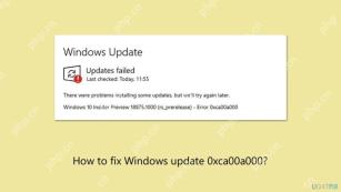 How to fix Windows update error 0xca00a000?May 02, 2025 pm 06:00 PM
Updates are vital to ensure that a Windows system runs well and is protected from potential outside threats, such as software vulnerabilities. Unfortunately, Wi
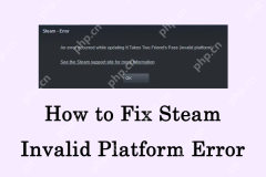 Learn How to Resolve Steam Invalid Platform Error on WindowsMay 01, 2025 pm 06:01 PM
Encountering the Steam "Invalid Platform" error? This MiniTool guide offers several solutions to get you back in the game. This frustrating error typically means your game is incompatible with your operating system. Understanding the Error
 How to fix Xbox app error 0x80073cf9 in Windows?May 01, 2025 am 02:00 AM
The Windows Xbox app lets you manage your Game Pass library, view friends, and launch PC games from one place. Its a hub of Microsofts gaming experience, especi
 Fix VMWare Slow System Performance in Windows 11Apr 30, 2025 pm 08:14 PM
VMware Workstation on Windows 11: Troubleshooting Slow Performance Experiencing sluggish system performance after installing VMware Workstation on your Windows 11 desktop? This guide offers practical solutions to resolve this common issue. Quick Nav
 Community Tips for Oblivion Remastered Low FPS/Stuttering PCApr 30, 2025 pm 08:13 PM
Many players have encountered frustrating low FPS, stuttering, and lagging issues in Oblivion Remastered. This MiniTool guide offers several effective solutions to boost your gameplay performance. Quick Navigation: Oblivion Remastered Performance Pr


Hot AI Tools

Undresser.AI Undress
AI-powered app for creating realistic nude photos

AI Clothes Remover
Online AI tool for removing clothes from photos.

Undress AI Tool
Undress images for free

Clothoff.io
AI clothes remover

Video Face Swap
Swap faces in any video effortlessly with our completely free AI face swap tool!

Hot Article
Hot Tools

DVWA
Damn Vulnerable Web App (DVWA) is a PHP/MySQL web application that is very vulnerable. Its main goals are to be an aid for security professionals to test their skills and tools in a legal environment, to help web developers better understand the process of securing web applications, and to help teachers/students teach/learn in a classroom environment Web application security. The goal of DVWA is to practice some of the most common web vulnerabilities through a simple and straightforward interface, with varying degrees of difficulty. Please note that this software

SAP NetWeaver Server Adapter for Eclipse
Integrate Eclipse with SAP NetWeaver application server.

Dreamweaver Mac version
Visual web development tools

Atom editor mac version download
The most popular open source editor

SublimeText3 Mac version
God-level code editing software (SublimeText3)

