


php editor Xinyi Asus motherboard jumper connection method? ASUS motherboard jumpers are important components used to adjust hardware devices or system settings. Correct wiring is crucial when building a computer or performing system maintenance. Improper wiring may cause the computer to fail to start properly or cause other problems. When wiring, first determine the settings that need to be adjusted, and then find the corresponding jumper positions according to the pin diagram in the motherboard manual. Be careful when wiring to ensure that the jumpers are connected correctly to avoid damaging the motherboard or other hardware devices.

How to connect the jumper on ASUS motherboard?
Motherboard jumper connection method:
1. POWER SW power switch, which controls the switch of the computer. It is generally a two-pin design, regardless of positive and negative poles; RESET SW restart switch, controls the computer to reset. Start up, regardless of positive and negative poles; HDD LED hard disk work indication, etc., shows the working status of the hard disk, divided into positive and negative poles, the indicator light will not light up if connected reversely; POWER LED power switch indicator light, shows whether the computer is powered on, divided into positive and negative poles , it will not light up if it is connected reversely; the SPEAK speaker has positive and negative poles, usually a four-pin interface, and it will not alarm if it is connected reversely.
2. The distribution of the main parts on the computer motherboard, including the CPU, memory, jumper connection locations, audio, etc.
3. The front USB connection is much simpler, because the chassis connection cable has changed from the original scattered multiple lines to an integrated design, and many motherboard USB pins are modular. The design is fixed in a module, making it easy to find the location.
4. For the connection of the front audio pins, mainstream motherboards nowadays basically use a fool-proof design with one hole left open. Just find the pin and plug it in directly.
How to plug in the power cord of ASUS motherboard?
1.
Tools/raw materials:
System version: windows10
Brand model: ASUS ASUS
Computer motherboard power cord Connection method:
Insert the power supply into the chassis.
2.
In the power cable, find the 24-pin cable that supplies power to the motherboard.
3.
In the motherboard, find the 24-pin power connector, insert the power cord into the motherboard, and pay attention to the position of the power cord's bayonet.
4.
In the power cable, find the 4-port cable that supplies power to the motherboard.
5.
On the motherboard, find the interface that supplies CPU power and connect the power cord to the motherboard.
6.
Find the hard drive power cord. It is connected to 4 wires and is flat in shape.
7.
Connect the hard disk cable to the power interface of the hard disk, paying attention to the direction of the power cable.
8.
Finally, connect another SATA power cable to the power interface of the optical drive.
How to connect the ASUS b85 pro gamer chassis jumper?
ASUS b85 pro gamer motherboard connection method:
1. Arrange all the cables together. According to the above labels, first clarify the definition of each cable:
a. Power switch: POWER SW, possible names: POWER, POWER SWITCH, ON/OFF, POWER SETUP, PWR, etc. Function definition: reset button on the front of the chassis.
b. Reset/restart switch: RESETSW, possible names: RESET, Reset Swicth, Reset Setup, RST, etc. Function definition: power-on button on the front of the chassis.
c. Power indicator: /- Possible names: POWER LED, PLED, PWRLED, SYS LED, etc.
d. Hard disk status indicator: HDD LED, Possible names: HD LED
e. Built-in small speaker (or alarm): SPEAKER, possible name: SPK, function definition: motherboard abnormality alarm.
f. Audio connection cable: AUDIO, possible name: FP AUDIO, function definition: chassis front audio, generally a whole.
g, USB connection to the front interface is generally a whole.
2. Find the location of each pin on the motherboard.
3. After all connecting cables are plugged in, check whether all hardware is installed correctly and is solid. Also check that all connections are correct and secure.
4. After the inspection is completed, press the power button on the chassis and check whether all the indicators are normal.
5. After the indicator light is normal, use a USB flash drive and headphones to check whether the front USB and front audio are normal.
6. Check that everything is normal and then cover the chassis. The cable connection work is completed.
Tips: Please perform all operations after the power is turned off.
How to connect the jumper on ASUS motherboard?
Motherboard jumper connection method:
1. POWER SW power switch, which controls the switch of the computer. It is generally a two-pin design, regardless of positive and negative poles; RESET SW restart switch, controls the computer to reset. Start up, regardless of positive and negative poles; HDD LED hard disk work indication, etc., shows the working status of the hard disk, divided into positive and negative poles, the indicator light will not light up if connected reversely; POWER LED power switch indicator light, shows whether the computer is powered on, divided into positive and negative poles , it will not light up if it is connected reversely; the SPEAK speaker has positive and negative poles, usually a four-pin interface, and it will not alarm if it is connected reversely.
2. The distribution of the main parts on the computer motherboard, including the CPU, memory, jumper connection locations, audio, etc.
3. The front USB connection is much simpler, because the chassis connection cable has changed from the original scattered multiple lines to an integrated design, and many motherboard USB pins are modular. The design is fixed in a module, making it easy to find the location.
4. For the connection of the front audio pins, mainstream motherboards nowadays basically use a fool-proof design with one hole left open. Just find the pin and plug it in directly.
Asus b365m-a motherboard pin wiring instructions?
ASUS b365m-a motherboard has a standard ATX interface, including a 24-pin main power interface, an 8-pin CPU power interface, a 4-pin auxiliary power interface, as well as multiple SATA interfaces, USB interfaces, etc. Before installation, you need to carefully read the motherboard manual, connect the motherboard and power supply according to the wiring diagram in the manual, and ensure that the power supply and motherboard are connected correctly. In addition, you also need to pay attention to the length of the power cord and the position of the cooling fan to ensure that the power cord can be smoothly connected to the motherboard and will not hinder the operation of the cooling fan.
How to connect jumpers on ASUS b250 motherboard?
Motherboard jumper connection method:
1. POWER SW power switch, which controls the switch of the computer. It is generally a two-pin design, regardless of positive and negative poles; RESET SW restart switch, controls the computer to reset. Start up, regardless of positive and negative poles; HDD LED hard disk work indication, etc., shows the working status of the hard disk, divided into positive and negative poles, the indicator light will not light up if connected reversely; POWER LED power switch indicator light, shows whether the computer is powered on, divided into positive and negative poles , it will not light up if it is connected reversely; the SPEAK speaker has positive and negative poles, usually a four-pin interface, and it will not alarm if it is connected reversely.
2. The distribution of the main parts on the computer motherboard, including the CPU, memory, jumper connection locations, audio, etc.
3. The front USB connection is much simpler, because the chassis connection cable has changed from the original scattered multiple lines to an integrated design, and many motherboard USB pins are modular. The design is fixed in a module, making it easy to find the location.
How to connect the jumper on ASUS a520m-k?
There are several jumpers on the ASUS A520M-K motherboard, including the CMOS clear jumper and the BIOS refresh jumper.
First, make sure the computer is turned off and unplugged.
To clear CMOS, move the cap of the CMOS clear jumper from the default position (usually pins 1-2) to the clear position (usually pins 2-3), wait a few seconds, and then move the cap Move back to default position.
To refresh the BIOS, move the BIOS refresh jumper cap from the default position to the refresh position, then turn on the computer and wait for the BIOS automatic refresh to complete.
When finished, shut down the computer, move the hat back to the default position, and restart the computer. Note that before doing these, make sure to read your motherboard manual for the correct jumper settings.
The above is the detailed content of How to connect jumpers on ASUS motherboard?. For more information, please follow other related articles on the PHP Chinese website!

 Clipchamp Video Loss on Windows? 2 Ways to Recover Files!May 09, 2025 pm 08:12 PM
Recover Lost Clipchamp Videos: A Step-by-Step Guide Losing a video you've edited in Clipchamp can be frustrating. This guide provides effective methods to recover your lost Clipchamp video files. Finding Your Clipchamp Videos Before attempting recov
 7 Useful Fixes for Action Center Keeps Popping upMay 09, 2025 pm 08:07 PM
Action Center allows you to access quick settings and notifications. However, some users say that they encounter the “Action Center keeps popping up” issue on Windows 11/10. If you are one of them, refer to this post from MiniTool to get solutions.Qu
 Instant Ways to Restore Missing Google Chrome Icon on WindowsMay 09, 2025 pm 08:06 PM
Troubleshoot Missing Google Chrome Icon on Windows Can't find your Google Chrome icon on Windows? This guide offers several solutions to restore it. Why is my Chrome icon missing? Several factors can cause the Chrome icon to vanish from your desktop:
 Brave Browser High CPU and RAM Usage: Best 5 Tips to ReduceMay 09, 2025 pm 08:05 PM
Brave browser CPU and memory usage too high? Under Windows 10/11 system, Brave browser's high CPU and memory usage problems have troubled many users. This tutorial will provide a variety of solutions to help you easily resolve this issue. Quick navigation: Brave browser high CPU and memory footprint Solution 1: Clear cookies and cache data Solution 2: Disable hardware acceleration Solution 3: Close the tab and update the Brave browser Solution 4: Disable the plugin Solution 5: Create a new user profile Optional: Run MiniTool System Booster System Optimization Tool Summarize Brave browser high CP
 Targeted Fixes for Xbox Error 0x87e0000f When Installing GamesMay 09, 2025 pm 08:04 PM
Troubleshooting Xbox Error Code 0x87e0000f: A Comprehensive Guide Encountering the Xbox error code 0x87e0000f while downloading games from Xbox Game Pass can be frustrating. This guide provides several solutions to help you resolve this issue and get
 OneDrive Couldn't Start Files on Demand?Top 4 MethodsMay 09, 2025 pm 08:02 PM
OneDrive Files On-Demand troubleshooting: resolving the "OneDrive couldn't start Files On-Demand" error. This MiniTool guide provides solutions for the persistent "Microsoft OneDrive Couldn’t start files on Demand" error (codes 0x
 How to fix 'Microsoft Store is blocked' error in Windows?May 09, 2025 pm 06:00 PM
Microsoft Store is blocked error occurs when Windows prevents access to the Microsoft Store app, displaying the message Microsoft Store is blocked. Check with y
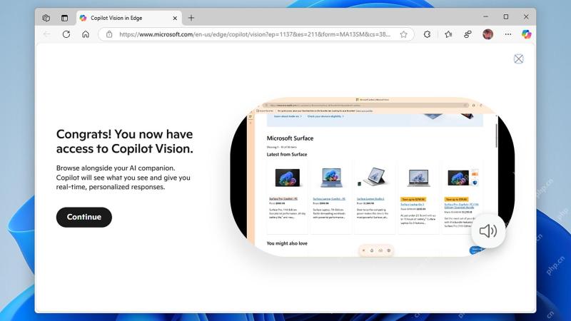 How to use Copilot Vision for free in Microsoft EdgeMay 09, 2025 am 10:32 AM
Staying current with all the new AI tools is a challenge. Many might even overlook readily available AI features. For instance, Copilot Vision is now free for all Microsoft Edge users – a fact easily missed if you don't regularly use Edge or haven't


Hot AI Tools

Undresser.AI Undress
AI-powered app for creating realistic nude photos

AI Clothes Remover
Online AI tool for removing clothes from photos.

Undress AI Tool
Undress images for free

Clothoff.io
AI clothes remover

Video Face Swap
Swap faces in any video effortlessly with our completely free AI face swap tool!

Hot Article
Hot Tools

VSCode Windows 64-bit Download
A free and powerful IDE editor launched by Microsoft

DVWA
Damn Vulnerable Web App (DVWA) is a PHP/MySQL web application that is very vulnerable. Its main goals are to be an aid for security professionals to test their skills and tools in a legal environment, to help web developers better understand the process of securing web applications, and to help teachers/students teach/learn in a classroom environment Web application security. The goal of DVWA is to practice some of the most common web vulnerabilities through a simple and straightforward interface, with varying degrees of difficulty. Please note that this software

Atom editor mac version download
The most popular open source editor

SublimeText3 English version
Recommended: Win version, supports code prompts!

Notepad++7.3.1
Easy-to-use and free code editor

