
 Web Front-endH5 TutorialIntroduction to SVG 2D in HTML5 6—Overview of window coordinate system, user coordinate system and transformation_html5 tutorial skills
Introduction to SVG 2D in HTML5 6—Overview of window coordinate system, user coordinate system and transformation_html5 tutorial skills

Coordinate system
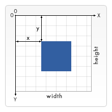
SVG has two coordinate systems: the window coordinate system and the user coordinate system. By default, the points in the user coordinate system and the view window coordinate system are in one-to-one correspondence, with the origin at the upper left corner of the view window, the x-axis horizontally to the right, and the y-axis vertically downward; as shown in the figure below:
The window position of SVG is generally specified by CSS, and the size is set by the width and height attributes of the SVG element. However, if the SVG is stored in an embedded object (such as an object element, or other SVG element), and the document containing the SVG is Formatted with CSS or XSL, and the CSS or other specified size values of these surrounding objects can already calculate the size of the viewport, the size of the surrounding object will be used at this time.
Here we need to distinguish between the concepts of window, window coordinate system and user coordinate system:
Window: refers to the visible rectangular area on the web page. The length and width are limited. This area is generally related to the size of the surrounding objects.
View window coordinate system: It is essentially a coordinate system with an origin, x-axis and y-axis; and it extends infinitely in two directions. By default, the origin is at the upper left corner of the viewport, the x-axis is horizontally to the right, and the y-axis is vertically downward. Points in this coordinate system can be transformed.
User coordinate system : It is essentially a coordinate system with an origin, x-axis and y-axis; and it extends infinitely in two directions. By default, the origin is at the upper left corner of the viewport, the x-axis is horizontally to the right, and the y-axis is vertically downward. Points in this coordinate system can be transformed.
By default, the window coordinate system coincides with the user coordinate system, but it should be noted here that the window coordinate system belongs to the element that creates the window. After the window coordinate system is determined, the coordinate tone of the entire window is determined. However, the user coordinate system belongs to each graphic element. As long as the graphics undergoes coordinate transformation, a new user coordinate system will be created. All coordinates and dimensions in this element use this new user coordinate system.
To put it simply: the window coordinate system describes the initial coordinate profile of all elements in the window, and the user coordinate system describes the coordinate profile of each element. By default, all elements use the default coordinate system that coincides with the window coordinate system. User coordinate system.
Coordinate space transformation
Let us review the transformation of canvas user coordinates. They are implemented through translation, scaling, and rotation functions; after each transformation, subsequent drawings The graphics work unless transformed again, which is the concept of the "current" user coordinate system. Canvas has only one user coordinate system.
In SVG, the situation is completely different. SVG itself is a vector graphic element, and its two coordinate systems can essentially be counted as "user coordinate systems"; both coordinate spaces of SVG can be transformed: window space transformation and user space transformation. Window space transformation is controlled by the viewBox attribute of the relevant elements (these elements create new windows); user space transformation is controlled by the transform attribute of the graphic element. View-space transformations are applied to the corresponding entire viewport, and user-space transformations are applied to the current element and its sub-elements.
View window transformation - viewBox property
All elements that can create a window (see the next section), plus marker, pattern, and view elements, have a viewBox attribute.
The format of the viewBox attribute value is (x0, y0, u_width, u_height). Each value is separated by commas or spaces. Together they determine the area displayed by the window: the coordinates of the upper left corner of the window are set to (x0, y0 ), the width of the window is set to u_width, and the height is u_height; this transformation affects the entire window.
Don’t be confused here: the size and position of the window have been determined by the element that creates the window and the surrounding elements (for example, the window created by the outermost svg element is determined by CSS, width and height), here The viewBox actually sets which part of the view window coordinate system can be displayed in this determined area.
The setting of viewBox actually includes two transformations: scaling and translation of the view window space.
The calculation of the transformation is also very simple: take the view window of the outermost svg element as an example, assuming that the width and length of the svg are set to width, height, and the viewBox is set to (x0, y0, u_width, u_height). Then the scaling ratios of the width and height of the drawn graphics are: width/u_width, height/u_height respectively. The coordinates of the upper left corner of the window are set to (x0,y0).
Experience the difference in the results drawn by the following codes:
You can see green and red rectangles in the picture drawn in the above example. In this case, the points in the window coordinate system still correspond to the points on the window one-to-one. This is also the default situation.
Above In the picture drawn by the example, you can only see the green rectangle, and the green rectangle displayed on the screen is 200*200 pixels. At this time, the coordinate points are no longer one-to-one correspondence, and the picture is enlarged.
In the picture drawn in the above example, the unit of the window coordinate system is reduced, so both rectangles are reduced.
In daily work, one of the tasks we often need to complete is to scale a group of graphics so that it fits its parent container. We can achieve this goal by setting the viewBox attribute.
Elements that create new windows
We can nest windows at any time. When a new window is created, a new window coordinate system and user coordinate system will also be created. Of course, new clipping paths will also be created. The following is a list of elements that can create new windows:
svg: svg supports nesting.
symbol: Creates a new window when instantiated by the use element.
image: A new window will be created when referencing the svg element.
foreignObject: Create a new window to render the objects inside.
Preserve the zoom ratio - preserveAspectRatio attribute
Sometimes, especially when using viewBox, we expect the graphics to occupy the entire view window, rather than pressing in both directions Same scaling. Sometimes, we want the graphics to be scaled at a fixed ratio in both directions. You can control this using the attribute preserveAspectRatio.
This attribute is available to all elements that can create a new window, plus image, marker, pattern, and view elements. And the preserveAspectRatio attribute will only take effect after the viewBox is set on the element. If the viewBox is not set, the preserveAspectRatio attribute is ignored.
The syntax of the attribute is as follows: preserveAspectRatio="[defer]
defer: Optional parameter, only valid for image elements. If the value of the preserveAspectRatio attribute in the image element starts with "defer", it means that the image element uses the scaling ratio of the referenced image, if it is referenced If the image has no scaling, "defer" is ignored. All other elements ignore this string.
align: This parameter determines the alignment of unified scaling, and can take the following values:
none - does not force unified scaling, so that the graphics can completely fill the entire viewport.
xMinYMin - Forces uniform scaling and aligns the
xMidYMin - Forces uniform scaling, and aligns the midpoint in the X direction of the vivowBox to the midpoint of the X direction in the viewport. In short, the midpoint in the X direction is aligned, and the Y direction is the same as above.
xMaxYMin - Forces uniform scaling and aligns the
Similar to other types of values: xMinYMid, xMidYMid, xMaxYMid, xMinYMax, xMidYMax, xMaxYMax. The meanings of these combinations are similar to those above.
meetOrSlice: optional parameter, you can set the following values:
meet - the default value, scale the graphics uniformly, so that all graphics are displayed in the viewport.
slice - Scale the graphics uniformly so that the graphics fills the viewport, and the excess parts are clipped.
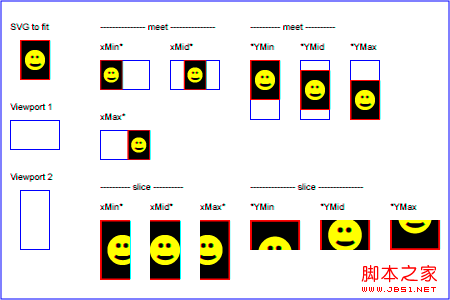
The following picture illustrates the effects of various fillings:
Transformation of user coordinate system - transform attribute
This type of transformation is specified by setting the transform attribute of the element. It should be noted here that the transformation of the element set by the transform attribute only affects the element and its sub-elements, and has nothing to do with other elements and does not affect other elements.
Translation - translate
Translation transformation translates the relevant coordinate value to the specified position. This transformation requires passing in the amount of translation on both axes. Look at the example:
This example draws a rectangle and places its starting point (0,0) translates to (30,40). Although the coordinate values of (x, y) can be set directly, it is also very convenient to use translation transformation. The second parameter of this transformation can be omitted and is treated as 0 by default.
Rotation - rotate
Rotating an element is also a very common task. We can use the rotate transformation to implement it, which requires passing in the angle parameter of the rotation. Look at the example:
This example will display a rectangle rotated 45 degrees. There are a few points to note:
1. The transformation here takes the angle value as a parameter.
2. Rotation refers to the rotation relative to the x-axis.
3. The rotation is carried out around the origin (0,0) of the user coordinate system.
skew - skew
transform also supports tilt transformation, which can be along the x-axis (tilt left and right, a positive angle is tilted to the right, which actually tilts y axis), or tilt along the y-axis (tilt up and down, a positive angle means downward tilt, which actually tilts the x-axis); this transformation requires passing in an angle parameter, which determines the angle of tilt. Look at the example below:
From the result, you can directly see the same size rectangle under different skew transformations Finally, the position and shape are obtained. Note here that the starting position of the rectangle has changed. This is because (30,30) is already at a different position in the new coordinate system.
Scale - scale
The scaling object is completed by the scaling transformation, which accepts 2 parameters, specifying the horizontal and vertical scaling ratios respectively. If the second If two parameters are omitted, it takes the same value as the first parameter. Look at the example below:
Transformation matrix - matrix
Anyone who has studied graphics knows that all transformations are actually represented by matrices, so the above transformations can actually be used A 3*3 matrix to represent:
a c e
b d f
0 0 1
Since only 6 values are used, it is also abbreviated as [a b c d e f]. Assigning matrix(a,b,c,d,e,f) to transfrom can implement the corresponding transformation. Transformation converts both coordinates and lengths to new dimensions. The matrices corresponding to the above various transformations are as follows:
Translation transformation [1 0 1 0 tx ty]:
1 0 tx
0 1 ty
0 0 1
Scale transformation [sx 0 0 sy 0 0]:
sx 0 0
0 sy 0
0 0 1
Rotation transformation [cos(a) sin(a) -sin(a) cos(a) 0 0]:
cos(a) -sin(a) 0
sin(a) cos(a) 0
00 1
Tilt along the 🎜>The code is as follows:
Copy code
The code is as follows:
The essence of transformation
When we summarized canvas earlier, we knew that various transformations act on the user coordinate system. In SVG, all transformations are also for two coordinate systems (essentially "user coordinate systems"). When the "transform" attribute is assigned to a container object or graphic object, or the "viewBox" attribute is assigned to "svg, symbol, marker, pattern, view", SVG will transform according to the current user coordinate system to create new user coordinates. system, and acts on the current object and its sub-objects. The coordinates and length units specified in the object no longer correspond to the peripheral coordinate system in a 1:1 ratio, but are converted to a new user coordinate system with the deformation; this new user coordinate system only acts on the current element and its sub-elements.
Transform chain
The transform attribute supports setting multiple transformations. These transformations only need to be separated by spaces and then placed together in the attribute. The execution effect is the same as executing these transformations independently in sequence.
The above effect is the same as the following:
Unit
Finally, let’s talk about the unit. Any coordinates and lengths can be brought and without units.
Without unit
Values without units are considered to have "user units", which are the unit values of the current user coordinate system.
With units
The relevant units in svg are the same as in CSS: em, ex, px, pt, pc, cm, mm and in. You can also use "%" for length.
Relative measurement units: em and ex are the same as in CSS, they are relative to the font-size and x-height of the current font.
Absolute measurement unit: One px is equal to one "user unit", that is, "5px" and "5" are the same. But whether a px corresponds to a pixel depends on whether some transformation has been performed.
The other units are basically multiples of px: 1pt=1.25px, 1pc=15px, 1mm=3.543307px, 1cm=35.43307px, 1in=90px.
If the width and height of the outermost SVG element do not specify a unit (that is, "user unit"), these values will be considered to be in px.
This article is a bit confusing. In fact, just remember that "the coordinates and length of graphic elements refer to the coordinates and length of the new user coordinate system after double transformation of the window coordinate system transformation and the user coordinate system transformation." That’s it.
Practical reference:
Script index: http://msdn.microsoft.com/zh-cn/library/ff971910(v=vs.85).aspx
Development Center: https://developer.mozilla.org/en/SVG
Popular Reference: http://www.chinasvg.com/
Official documentation: http://www.w3.org/TR/SVG11/

 HTML5: The Standard and its Impact on Web DevelopmentApr 27, 2025 am 12:12 AM
The core features of HTML5 include semantic tags, multimedia support, offline storage and local storage, and form enhancement. 1. Semantic tags such as, etc. to improve code readability and SEO effect. 2. Simplify multimedia embedding with labels. 3. Offline storage and local storage such as ApplicationCache and LocalStorage support network-free operation and data storage. 4. Form enhancement introduces new input types and verification properties to simplify processing and verification.
 H5 Code Examples: Practical Applications and TutorialsApr 25, 2025 am 12:10 AM
H5 provides a variety of new features and functions, greatly enhancing the capabilities of front-end development. 1. Multimedia support: embed media through and elements, no plug-ins are required. 2. Canvas: Use elements to dynamically render 2D graphics and animations. 3. Local storage: implement persistent data storage through localStorage and sessionStorage to improve user experience.
 The Connection Between H5 and HTML5: Similarities and DifferencesApr 24, 2025 am 12:01 AM
H5 and HTML5 are different concepts: HTML5 is a version of HTML, containing new elements and APIs; H5 is a mobile application development framework based on HTML5. HTML5 parses and renders code through the browser, while H5 applications need to run containers and interact with native code through JavaScript.
 The Building Blocks of H5 Code: Key Elements and Their PurposeApr 23, 2025 am 12:09 AM
Key elements of HTML5 include,,,,,, etc., which are used to build modern web pages. 1. Define the head content, 2. Used to navigate the link, 3. Represent the content of independent articles, 4. Organize the page content, 5. Display the sidebar content, 6. Define the footer, these elements enhance the structure and functionality of the web page.
 HTML5 and H5: Understanding the Common UsageApr 22, 2025 am 12:01 AM
There is no difference between HTML5 and H5, which is the abbreviation of HTML5. 1.HTML5 is the fifth version of HTML, which enhances the multimedia and interactive functions of web pages. 2.H5 is often used to refer to HTML5-based mobile web pages or applications, and is suitable for various mobile devices.
 HTML5: The Building Blocks of the Modern Web (H5)Apr 21, 2025 am 12:05 AM
HTML5 is the latest version of the Hypertext Markup Language, standardized by W3C. HTML5 introduces new semantic tags, multimedia support and form enhancements, improving web structure, user experience and SEO effects. HTML5 introduces new semantic tags, such as, ,, etc., to make the web page structure clearer and the SEO effect better. HTML5 supports multimedia elements and no third-party plug-ins are required, improving user experience and loading speed. HTML5 enhances form functions and introduces new input types such as, etc., which improves user experience and form verification efficiency.
 H5 Code: Writing Clean and Efficient HTML5Apr 20, 2025 am 12:06 AM
How to write clean and efficient HTML5 code? The answer is to avoid common mistakes by semanticizing tags, structured code, performance optimization and avoiding common mistakes. 1. Use semantic tags such as, etc. to improve code readability and SEO effect. 2. Keep the code structured and readable, using appropriate indentation and comments. 3. Optimize performance by reducing unnecessary tags, using CDN and compressing code. 4. Avoid common mistakes, such as the tag not closed, and ensure the validity of the code.
 H5: How It Enhances User Experience on the WebApr 19, 2025 am 12:08 AM
H5 improves web user experience with multimedia support, offline storage and performance optimization. 1) Multimedia support: H5 and elements simplify development and improve user experience. 2) Offline storage: WebStorage and IndexedDB allow offline use to improve the experience. 3) Performance optimization: WebWorkers and elements optimize performance to reduce bandwidth consumption.


Hot AI Tools

Undresser.AI Undress
AI-powered app for creating realistic nude photos

AI Clothes Remover
Online AI tool for removing clothes from photos.

Undress AI Tool
Undress images for free

Clothoff.io
AI clothes remover

Video Face Swap
Swap faces in any video effortlessly with our completely free AI face swap tool!

Hot Article
Hot Tools

mPDF
mPDF is a PHP library that can generate PDF files from UTF-8 encoded HTML. The original author, Ian Back, wrote mPDF to output PDF files "on the fly" from his website and handle different languages. It is slower than original scripts like HTML2FPDF and produces larger files when using Unicode fonts, but supports CSS styles etc. and has a lot of enhancements. Supports almost all languages, including RTL (Arabic and Hebrew) and CJK (Chinese, Japanese and Korean). Supports nested block-level elements (such as P, DIV),
ZendStudio 13.5.1 Mac
Powerful PHP integrated development environment

Dreamweaver CS6
Visual web development tools

MantisBT
Mantis is an easy-to-deploy web-based defect tracking tool designed to aid in product defect tracking. It requires PHP, MySQL and a web server. Check out our demo and hosting services.

SecLists
SecLists is the ultimate security tester's companion. It is a collection of various types of lists that are frequently used during security assessments, all in one place. SecLists helps make security testing more efficient and productive by conveniently providing all the lists a security tester might need. List types include usernames, passwords, URLs, fuzzing payloads, sensitive data patterns, web shells, and more. The tester can simply pull this repository onto a new test machine and he will have access to every type of list he needs.

