
 Technology peripheralsAIImproving HoloLens internal PCIe data link transmission: Microsoft shares AR/VR patents
(Nweon December 27, 2023) A wired connection is often called a "hard link", which physically connects one node to another node. One wired connection is PCIe. PCIe is an interface used to connect high-speed nodes, and while high-speed connection terminals and protocols such as PCIe offer substantial advantages, these types of terminals require high power to operate. For a battery-powered computing architecture like a headset, this would place a huge burden on the system.
In a patent application titled "Error recovery and power management between nodes of an interconnection network", Microsoft describes improving the connection between transmitter nodes and receiver nodes by recovering from error conditions without the need to retransmit data. transmission method to help reduce the system burden on the headset.
In one embodiment, start data streaming. The data stream includes different types of data packets. Error correcting code (ECC) is optionally applied to control data type packets. The transmitter node and the receiver node are connected through hard links with multiple virtual channels. Each virtual channel is associated with a corresponding power consumption node.
When the receiver node receives a control data type packet, error correction is performed without retransmission if necessary. When sending the final data type packet for each virtual channel, the sender node sends the end condition type packet. The corresponding power consumption node corresponding to the corresponding virtual channel transitions from the active state to the low power state.
Certain embodiments are configured to improve power usage of battery-powered devices by identifying when packet transmission across a virtual channel is complete, and by causing the node to enter a low power state when the packet transmission is complete.

An example of an interconnection network 200 is shown here, as shown in Figure 2. Interconnection network 200 may contain any number of interconnection nodes, such as node 205 and node 210. Nodes 205 and 210 can be various types of computing components, such as HPU holographic processing units
As shown in the figure, node 205 is connected to node 210 through high-speed link 215. High speed link 215 may be any type of physical channel connection that supports high speed data transmission.
The described embodiments may virtualize high speed link 215 to include any number of virtual channels. For example, hard link 240 represents high speed link 215. Hard link 240 is shown to include any number of virtual channels, such as virtual channels 245, 250, 255, and 260. Packets are shown traveling through these different virtual channels, such as packet 265.
Each virtual channel is associated with its respective buffer. For example, virtual channel 245 may be associated with buffer 270, and virtual channel 250 may be associated with buffer 275. Other virtual channels are associated with their respective buffers. Each buffer can have a corresponding buffer size of 280. According to the inventive principle, the hardware is capable of maintaining channel bandwidth balance among various requesters (i.e., receiving nodes).


Figures 3 and 4 are examples of head-mounted displays.
High-speed link 410A may be used to transmit high-speed display data and/or sensor data between a computing unit located in the front-end housing and a computing unit located in the rear-end housing. High-speed link 410A is designed to have low latency so that it can pass large numbers of computing cycles or communications. In contrast, low-speed link 405A can be used to provide power, ground or switching mechanisms.
High-speed link 215 in Figure 2 may represent high-speed link 410A in Figure 4, and nodes 205 and 210 in Figure 2 may represent any computing unit shown in Figure 4, such as display circuit 420A, CPU 420B and 440A, GPU 420C and 4406, SOC 420D and HPU 440C.

Figure 8 lists operational requirements 800. Initially, operational requirements 800 include real-time data requirements 805 . As discussed earlier about headsets, the headset used to display content to the user has real-time requirements 805, so it is desirable to avoid retransmitting data
In addition, the content of the headset will dynamically change based on many different factors, including the posture/orientation of the headset, scene changes in the MR scene, interaction with holograms, etc. So when implemented in a headset, data transfer from one node to another in the headset can be required to satisfy real-time data requirements 805 . This means that headset implementations now do not have the ability to retransmit data, as traditional systems do when encountering data errors.
Due to live data request 805, retransmissions to resolve or correct errors are not available. Therefore, Microsoft's invention introduces a new technology to respond to errors.
In addition, operational requirements 800 include low-overhead requirements 810. As mentioned before, hard links between nodes have limited bandwidth. The principle described in the invention provides an error correction technology that not only meets the real-time data requirements 805, but also can place a small amount of extra overhead in the bus protocol.
800 Operational requirements also need to include low power consumption requirements 815. Depending on the specific characteristics of the data flow, embodiments may selectively turn off power consuming nodes to reduce power consumption. For example, in a head-mounted display environment, embodiments may cause the laser to enter a low-power state by detecting specific data packets transmitted between nodes

In order to achieve the above requirements, embodiments cause specific types of data packets to be transmitted from one node to another node in the data flow. FIG. 9 shows an example package 900 that is representative of the package discussed in FIG. 2 . It is worth noting that the data packet 900 can take different forms, including a control data type data packet 905, a non-control data type data packet 910, and an end condition data packet 915.
After all virtual channels have completed sending their respective data streams, the last virtual channel that has completed sending its data stream sends an additional final end condition packet to give the status of all virtual channels. The sending node does not send any new traffic for the virtual channel until all virtual channels have completed transmitting their respective data streams for the scan. When a new scan is initiated or a new frame is initiated, the virtual channel will start sending packets again.
Control data type package 905 is a package type used to control how specific operations are performed. For example, referring to the header display example, the control data type packet 905 may contain information about when the laser is fired, timing information, payload type information, virtual channel information, and may further include information about where the laser pulse is placed.
The control data type packet 905 may also include header information indicating which channel or virtual channel to use. For example, each laser of the headset could be associated with its own virtual channel. Control data type packet 905 may include control information for the corresponding laser of the virtual channel and virtual channel information
Due to the importance of the control data type packet 905, the packet is protected using the error correction code ECC 925. To clarify, since the time and location information contained in the control data type packet 905 is differentially compressed and very important, ECC 925 is used to protect the data from errors that may occur during transmission.
If errors are allowed in the data contained in the control data type packet 905, the entire scan may be corrupted, causing artifacts to be introduced into the resulting image frames.

Figure 10 provides additional description of ECC 1000, which represents ECC 925 of Figure 9. Specifically, ECC 1000 includes at least two types of protection, including single-bit error correction 1005 and double-bit error correction 1010.
In one embodiment, the error protection is x bit error correction and x 1 bit error detection. Select ECC 1000 to ensure ECC 1000 supports error rates. The ECC 1000 is available with 8 bits per control data type packet, or other number of bits selected depending on the length of the control data type packet.
Returning to Figure 9, the non-control data type packet 910 is a packet containing payload information, such as how to illuminate a specific pixel in the scan, such as color intensity, duration, laser pulse size, etc. As such, the non-control data type packet 910 includes pixel data 930 describing the mechanism of how the pixel is illuminated.
Although a single control data type packet can be sent over the virtual channel in each new data flow, any number of non-control data type packets may be sent in the data flow. Additionally, corruption of any single non-control data type packet may result in corruption of only a single pixel.
Headset refresh rates typically range from 90 Hz to 120 Hz, and the resolution is very high, so users may not notice the damage to individual pixels. Given these conditions, embodiments selectively avoid imposing ECC on non-control data type packets 910. Errors that occur in non-control data type packet 910 can be simply accepted because the impact of these errors is minimal
By applying ECC 925 to the control data type packet 905, since ECC 925 allows error correction and detection at the receiving node, there is no need to retransmit the control data type packet 905, and real-time processing can be performed, thereby satisfying the requirements in Figure 8 Real-time data requirements 805.
By applying ECC 925 only to control data type packets 905 and not to non-control data type packets 910, embodiments meet the low overhead requirement 810 because the additional data only applies to a single packet rather than multiple data pack. Therefore, the additional overhead is also negligible
Additionally, by applying ECC, embodiments are able to automatically recover when an error is detected, thus meeting the automatic hardware recovery requirement 825. Therefore, embodiments impose different data protection requirements based on data type or rather different data packet types.
End condition package 915 is a package used to trigger when the data flow is completed. In other words, when all non-control data type packets have been sent, the end condition packet 915 will be sent as the last packet of the data flow
If no pixels are illuminated by a specific laser in a specific scan, there may be no control data type packets or non-control data type packets transmitted on the laser's corresponding virtual channel. Instead, only end condition packet 915 can be sent. To help mitigate possible errors, multiple end condition packets can be transmitted.

Figure 11 shows an example scenario involving multiple virtual channels 1100 and the three different packet types introduced in Figure 10 are being transmitted. Figure 11 shows a scenario with 12 virtual channels and data flow flowing from left to right. Additionally, different bag types are illustrated using different shading techniques. In this example scenario, each virtual channel corresponds to a single laser in the headset, and each virtual channel has its own corresponding data stream being transmitted.
Figure 11 shows how the data flow for Channel 1 starts with a control data type packet, then includes five non-control data type packets, and then includes an end condition packet. Channel 2 is similar, it includes a control data type packet, two non-control data type packets and an end condition packet. Channel 1 and Channel 2 are transmitting data because the laser corresponding to the channel will be used to illuminate the pixels in the scan.
Channel 3, on the other hand, corresponds to the laser that will not be used to illuminate the scanned pixels. Therefore, the data stream transmitted through channel 3 only includes an end condition packet. This end condition packet usefully informs that the corresponding laser will not be used for this particular scan.
Accordingly, if the laser is not intended to be used during a specific scan, the data stream transmitted through the laser's virtual channel will only include one or more end condition packets

Figure 12 focuses on virtual channel 1200, which represents virtual channel 1100 in Figure 11. Figure 12 shows how the end condition packet is transmitted over channel 1. The end condition packet operates as a trigger 1210 to notify the system that the corresponding power consumption node can transition from the power consumption mode to the reduced power consumption mode. This triggering is beneficial because the system now knows that the power node is idle and can transition to a reduced power mode.
For example, in a head-mounted display environment, the head-mounted display includes a laser transmitter 1215, which itself includes lasers 1215A, 1215B, and 1215C. Channel 1 is a virtual channel specifically corresponding to laser 1215A. Transmitting a terminal condition packet over Channel 1 causes the system to recognize that use of laser 1215A is now complete and therefore can transition from active mode 1220 of generating laser light to low power mode 1225 or possibly even off mode 1230.
As shown in Figure 12, the end condition has been triggered, causing laser 1215A to stop emitting laser light, while lasers 1215B and 1215C may still continue to emit laser light. According to Figure 11, by transmitting the end status data packet in each different virtual channel, the node corresponding to each virtual channel enters a low power consumption state, thereby maintaining the system's power
Simply turning back to Figure 11, channel 1 is shown as the last channel transmitting the end condition packet. No matter which virtual channel transmits the end condition data packet last, the task of the data flow of the virtual channel is to perform the so-called encapsulation operation, in which the end condition data packet constitutes the "final" end condition type data packet 1315, as shown in Figure 13
The final end condition type packet 1315 provides additional information to the receiving node indicating that all data flows for all other virtual channels have been completed. This functionality is beneficial in a head-mounted display environment because the final End Condition Type Packet 1315 signals the end of the scan.
Related Patents: Microsoft Patent | Error recovery and power management between nodes of an interconnection network
Microsoft patent application titled "Inter-node Error Recovery and Power Management" was originally filed in August 2023 and recently published by the U.S. Patent and Trademark Office
It should be noted that, generally speaking, after a U.S. patent application is reviewed, it will be automatically published 18 months from the filing date or priority date, or it will be published within 18 months from the filing date at the request of the applicant. Note that publication of a patent application does not mean that the patent is approved. After a patent application is filed, the USPTO requires actual review, which can take anywhere from 1 to 3 years.
In addition, this is just a patent application, there is no guarantee that it will be approved, and it cannot be determined whether it will be truly commercialized and produce practical application effects
The above is the detailed content of Improving HoloLens internal PCIe data link transmission: Microsoft shares AR/VR patents. For more information, please follow other related articles on the PHP Chinese website!

 微软深化与 Meta 的 AI 及 PyTorch 合作Apr 09, 2023 pm 05:21 PM
微软宣布进一步扩展和 Meta 的 AI 合作伙伴关系,Meta 已选择 Azure 作为战略性云供应商,以帮助加速 AI 研发。在 2017 年,微软和 Meta(彼时还被称为 Facebook)共同发起了 ONNX(即 Open Neural Network Exchange),一个开放的深度学习开发工具生态系统,旨在让开发者能够在不同的 AI 框架之间移动深度学习模型。2018 年,微软宣布开源了 ONNX Runtime —— ONNX 格式模型的推理引擎。作为此次深化合作的一部分,Me
 微软提出自动化神经网络训练剪枝框架OTO,一站式获得高性能轻量化模型Apr 04, 2023 pm 12:50 PM
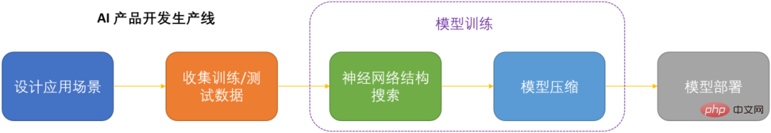
OTO 是业内首个自动化、一站式、用户友好且通用的神经网络训练与结构压缩框架。 在人工智能时代,如何部署和维护神经网络是产品化的关键问题考虑到节省运算成本,同时尽可能小地损失模型性能,压缩神经网络成为了 DNN 产品化的关键之一。DNN 压缩通常来说有三种方式,剪枝,知识蒸馏和量化。剪枝旨在识别并去除冗余结构,给 DNN 瘦身的同时尽可能地保持模型性能,是最为通用且有效的压缩方法。三种方法通常来讲可以相辅相成,共同作用来达到最佳的压缩效果。然而现存的剪枝方法大都只针对特定模型,特定任务,且需要很
 超5800亿美元!微软谷歌神仙打架,让英伟达市值飙升,约为5个英特尔Apr 11, 2023 pm 04:31 PM
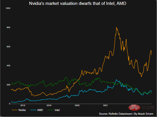
ChatGPT在手,有问必答。你可知,与它每次对话的计算成本简直让人泪目。此前,分析师称ChatGPT回复一次,需要2美分。要知道,人工智能聊天机器人所需的算力背后烧的可是GPU。这恰恰让像英伟达这样的芯片公司豪赚了一把。2月23日,英伟达股价飙升,使其市值增加了700多亿美元,总市值超5800亿美元,大约是英特尔的5倍。在英伟达之外,AMD可以称得上是图形处理器行业的第二大厂商,市场份额约为20%。而英特尔持有不到1%的市场份额。ChatGPT在跑,英伟达在赚随着ChatGPT解锁潜在的应用案
 竞争加剧,微软和Adobe发布AI图像生成工具Apr 11, 2023 pm 10:55 PM
随着OpenAI DALL-E和Midjourney的推出,AI艺术生成器开始变得越来越流行,它们接受文本提示并将其变成美丽的、通常是超现实的艺术品——如今,有两家大企业加入了这一行列。微软宣布,将通过Bing Image Creator把由DALL-E模型提供支持的AI图像生成功能引入Bing搜索引擎和Edge浏览器。创意软件开发商Adobe也透露,将通过名为Firefly的AI艺术生成产品来增强自己的工具。对于有权访问Bing聊天预览的用户来说,这一新的AI图像生成器已经可以在“创意”模式下
 NLP模型读不懂人话?微软AdaTest挑错效率高五倍Apr 09, 2023 pm 04:11 PM
自然语言处理(NLP)模型读不懂人话、将文本理解为相反的意思,是业界顽疾了。 现在微软表示,开发出解决此弊的方法。微软开发AdaTest方法来测试NLP模型 可作为跨越各种应用基础的大型模型,或称平台模型的进展已经大大改善了AI处理自然语言的能力。但自然语言处理(NLP)模型仍然远不完美,有时会以令人尴尬的方式暴露缺陷。 例如有个顶级的商用模型,将葡萄牙语中的「我不推荐这道菜」翻译成英语中的「我非常推荐这道菜」。 这些失败之所以继续存在,部分原因是寻找和修复NLP模型中的错误很难,以至于严重的
 微软出品的Python小白神器,真香!Apr 12, 2023 am 10:55 AM
大家好,我是菜鸟哥!最近逛G网,发现微软开源了一个项目叫「playwright-python」,作为一个兴起项目。Playwright 是针对 Python 语言的纯自动化工具,它可以通过单个API自动执行 Chromium,Firefox 和 WebKit 浏览器,连代码都不用写,就能实现自动化功能。虽然测试工具 selenium 具有完备的文档,但是其学习成本让一众小白们望而却步,对比之下 playwright-python 简直是小白们的神器。Playwright真的适用于Python吗?
 微软必应再强化!接入OpenAI DALL·E模型,文字生成图像Mar 31, 2023 pm 10:39 PM
微软必应完善文字生成图像能力,Adobe 今日也发布 Firefly,杀入生成式 AI 这场游戏。 昨晚实在是有些热闹。一边英伟达 GTC 正在进行中,一边谷歌正式开放了 Bard 的测试,这里微软必应也不甘寂寞。今日,微软正式宣布,必应搜索引擎接入了 OpenAI 的 DALL·E 模型,增加了 AI 生成图像的功能。也就是说,在接入 ChatGPT 之后,必应再次强化,Bing Image Creator 能够让用户用 DALL·E 模型生成图像。「对于拥有必应预览版权限的用户,Bing I
 微软推出AI工具Security Copilot,帮助网络安全人员应对威胁Apr 04, 2023 pm 02:50 PM
近日微软推出了Security Copilot,这款新工具旨在通过AI助手简化网络安全人员的工作,帮助他们应对安全威胁。 网络安全人员往往要管理很多工具,和来自多个来源的海量数据。近日微软宣布推出了Security Copilot,这款新工具旨在通过AI助手简化网络安全人员的工作,帮助他们应对安全威胁。Copilot利用基于OpenAI的GPT-4最新技术,让网络安全人员能够就当前影响环境的安全问题提问并获得答案,甚至可以直接整合公司内部的知识,为团队提供有用的信息,从现有信息中进行学习,将当前


Hot AI Tools

Undresser.AI Undress
AI-powered app for creating realistic nude photos

AI Clothes Remover
Online AI tool for removing clothes from photos.

Undress AI Tool
Undress images for free

Clothoff.io
AI clothes remover

AI Hentai Generator
Generate AI Hentai for free.

Hot Article
Hot Tools

MinGW - Minimalist GNU for Windows
This project is in the process of being migrated to osdn.net/projects/mingw, you can continue to follow us there. MinGW: A native Windows port of the GNU Compiler Collection (GCC), freely distributable import libraries and header files for building native Windows applications; includes extensions to the MSVC runtime to support C99 functionality. All MinGW software can run on 64-bit Windows platforms.

SAP NetWeaver Server Adapter for Eclipse
Integrate Eclipse with SAP NetWeaver application server.

MantisBT
Mantis is an easy-to-deploy web-based defect tracking tool designed to aid in product defect tracking. It requires PHP, MySQL and a web server. Check out our demo and hosting services.

Dreamweaver CS6
Visual web development tools

SublimeText3 Mac version
God-level code editing software (SublimeText3)

