


(Nweon October 19, 2023) Depth sensing systems such as time-of-flight ToF cameras can be used to generate depth images of the environment for HoloLens 2, where each pixel of the depth image represents a corresponding point in the environment distance. In ToF imaging, the distance of a point on the imaging surface in the environment depends on the length of the time interval for the light from the ToF camera to travel to that point and then return to the ToF camera sensor.
Phase-based ToF imaging is a variant of ToF imaging in which depth is calculated based on the phase shift of amplitude-modulated light reflected back from the object. Due to the movement of the ToF camera between phase data acquisitions, intra-frame phase data may be relatively shifted. For example, in a first intra-frame phase data acquisition, a pixel may sense phase data at a first modulation frequency at a location within the scene. Then during phase data acquisition within the next frame, the pixels can sense phase data at a different scene location at a second modulation frequency. The phase data at different frequencies becomes inconsistent, which can be called motion blur.
So in the patent application titled "Motion correction for time-of-flight depth imaging", Microsoft proposed a motion correction method for ToF imaging.
To do this, the active brightness AB image corresponding to the first illumination light modulation frequency is compared with the AB image corresponding to the second illumination light modulation frequency to determine the intra-frame two-dimensional translation. Intra-frame 2D translation corresponds to the estimated motion of the camera relative to the imaged scene.
Intra-frame 2D translation is then applied to the phase data to help align the phase images and form corrected phase data. Next, phase unpacking is performed on the corrected phase data to obtain an intra-frame corrected three-dimensional depth image. Intra-frame 2D translation can also be used to perform motion correction on intra-frame AB images. For example, the intra-frame corrected AB image can be obtained by averaging the corrected AB images.
In such an example, the first AB image from the first frame is compared to the second AB image from the second frame to determine the inter-frame 2D translation. Inter-frame translation is an estimate of motion between frames. An inter-frame 2D translation can then be applied to the depth image of the first frame to form an inter-frame generated depth image. The inter-frame two-dimensional translation can be determined from the intra-frame corrected AB image.
Additionally, as an estimate of camera motion, inter-frame 2D translation can be output and used in various temporal post-processing routines or software services. Therefore, the embodiments described in the patent can help achieve motion blur correction of 3D depth data using 2D intra-frame AB image data. By using 2D data, motion correction can be performed in real time with relatively efficient computational performance compared to using 3D depth data for motion blur correction.

Figure 2 shows an example including a ToF camera 202. Among them, the ToF camera is a phase-based ToF depth imaging system 200 . ToF camera 202 includes a sensor array 204 including a plurality of ToF pixels 206 each configured to acquire a light sample that captures phase data, a controller 208 and an objective system 210 .
The controller 208 is configured to collect and process data from the ToF pixels 206 of the sensor array 204 to construct a depth image. Controller 208 may include executable instructions to perform denoising and/or phase unwrapping.
Depth imaging system 200 includes both a modulated light emitter 230 and an analog and/or digitally modulated electronic shutter 232 for sensor array 204 to control the integration of light through sensor array 204. Modulated light emitter 230 may be configured to emit electromagnetic radiation with any frequency detectable by ToF pixel 206 .
The modulated light may be modulated at different frequencies sequentially or simultaneously, and the sensor array 204 is configured to sample the light reflected from the modulated light emitter 230 to the surface 220 and back to the camera. Each ToF sensing pixel 206 of sensor array 204 may include one or more pixel taps to integrate reflected light signals at different time intervals and thereby determine phase shifts.
For each modulation frequency, the sensor array 204 is controlled to sample the light at multiple phase angles of the amplitude-modulated light from the light source and determine the light for each modulation frequency from the multiple light samples for the modulation frequency. phase samples. The phase samples can then be unwrapped to obtain a depth value for each pixel.
Due to the periodicity of the modulated light, the total phase measured repeats every 2π. Since n(k) cannot be directly measured by phase-based ToF pixels, the total phase and therefore the actual distance associated with the measurement are ambiguous. Therefore in phase-based ToF imaging, the distance that can be measured (blur-free range) is limited by the modulation frequency.
Two or more different modulation frequencies can be used to increase the ambiguity-free range, and then the collected phase shift data can be spread out to accurately determine distance.

Figure 3 schematically illustrates example ToF image data 300 for a plurality of K modulation frequencies. Data 300 represents data that can be acquired by the depth imaging system 200 during multi-frequency frame acquisition.
In the example shown, the depth data includes an M×N array of data for each of the K modulation frequencies, resulting in an M×N grid of intra-frame depth data 302a-c, where each mesh Each pixel 304 in the grid represents a measurement value obtained at a corresponding illumination light modulation frequency K of K modulation frequencies.
The measured phase is used to calculate the depth value associated with the pixel. But as mentioned above, in phase-based ToF imaging, the distance that can be measured (blur-free range) is limited by the modulation frequency. Therefore, a set of K ≥ 2 modulation frequencies K can be used to increase the range, allowing the phase information to be unraveled to accurately determine distance.
Phase unwrapping is a method of disambiguating phase shift data and identifying correct distance values by illuminating a scene with multiple amplitude-modulated lights of different frequencies, since the distance ambiguity is different for each frequency of illumination light.
But as mentioned above, if the ToF depth camera is in motion, phase unwrapping errors may occur. Since the depth data acquisition at each frequency is performed sequentially, the phase image and AB image are temporarily separated within one frame.
For example, intra-frame phase image 306a may include first frequency ƒ1 phase data acquired toward the beginning of the frame, and intra-frame phase image 306b may include second frequency ƒ2 phase data acquired toward the middle of the frame, intra-frame Phase image 306b may include third frequency ƒ3 phase data acquired toward the end of the frame.
Therefore, if the ToF depth camera moves between intra-frame acquisitions, the phase data at the three different frequencies may be shifted and misaligned. Inconsistent phase data can lead to errors in phase unrolling.
So, Microsoft proposed a solution that uses AB image data to estimate motion and determine two-dimensional translation.
The company notes that while depth data can be used, determining 2D translation based on AB image data may be more robust due to active brightness differences between objects in the scene. Intra-frame motion correction can then be performed on the phase data using 2D translation. Performing phase unwrapping on intra-frame corrected phase data can help avoid unwrapping errors due to motion blur.

Figure 4 shows an example method for performing such correction on depth data prior to phase unwrapping. Method 400 may be implemented in a computing system that receives data from a ToF depth camera.
At 402, multi-frequency frame collection is performed, in which multiple intra-frame phase samples are collected by the ToF image sensor. Intra-frame phase samples are collected for each of a plurality of illumination light modulation frequencies (ƒ1, ƒ2, ƒ3) to form corresponding intra-frame depth data 404a-c. In this example, intra-frame depth data 404a is obtained first, intra-frame depth data 404b is obtained secondly, and intra-frame depth data 404c is obtained thirdly, as shown by the time arrow.
At 406, signal calibration correction is performed to obtain phase data 408 and active brightness data 410. As mentioned above, intra-frame depth data at different frequencies may be relatively shifted due to camera motion. Therefore, method 400 compares active brightness data 410 to estimate and correct for motion.
Here, the intra-frame AB image 410a is compared with the intra-frame AB image 410b to determine the first intra-frame two-dimensional translation 412. The two-dimensional translation from AB1 to AB2 can be expressed as [Δu, Δv]1,2, where Δu is the pixel displacement in the x direction and Δv is the pixel displacement in the y direction. Intra-2D translation 412 is an estimate of motion between intra-frame depth data 404a and intra-frame depth data 404b.
Next, the intra-AB image 410a is compared to the intra-AB image 410c to determine a second intra-frame 2D translation 414, denoted as [Δu, Δv] 13.
In one embodiment, intra-AB image 410b may be compared to intra-AB image 410c to determine a third intra-frame two-dimensional translation. In other examples, any suitable intra-frame AB image pairs may be compared to determine corresponding intra-frame 2D translations. Any suitable method can be used to compare the AB images and determine the translation. In one example, features are extracted from AB images, formed into feature maps, and used to compare images.
After determining the 2D translation, the phase data can be corrected using the determined translation. In the embodiment shown in FIG. 4 , intra-frame two-dimensional translation 412 is applied to the phase image 408b to correct the phase image to form a corrected phase image 420b. Similarly, intra-frame two-dimensional translation 414 is performed on the phase image 408c to correct the phase image, forming a corrected phase image 420c.
Therefore, the corrected phase data 420 represents the phase data that has been "realigned" to the phase image 408a. In one example, one or more two-dimensional translations may be applied to form a corrected phase image aligned with phase image 408b or 408c.
At 422, method 400 also includes performing phase unwrapping on the corrected phase data 420 to form a depth image 424. Since the corrected phase images 420b, 420c can be realigned with the phase image 408a, the phase unwrapping at 422 can produce relatively less unwrapping error than in the example where motion blur correction is ignored.
So, method 400 can help achieve better performance in processing depth data 404 to form depth image 424.
Additionally, the application of intra-frame 2D translation can be performed via convolution and thus can be combined with spatial and temporal filtering processes that also utilize convolution. At the same time, as an estimate of camera motion, the determined intra-frame 2D translation may be useful for various post-processing applications, such as temporal filters, trajectory estimation, dynamic region estimation or mapping. Similar techniques can be used to correct intra-AB images and form intra-corrected AB images.

Referring to Figure 5, method 500 utilizes intra-frame two-dimensional translation 412, 414 to form corrected AB data 510. In one example, method 500 is performed together with method 400. In other examples, method 500 is performed separately from method 400 .
As shown in Figure 5, the intra-frame two-dimensional translation 412 is applied to the intra-frame AB image 410b to correct the image to form a corrected AB image 510b. Further, intra-frame two-dimensional translation 414 is applied to AB image 410c to form corrected AB image 510c. Together with intra-AB image 408a, corrected AB images 510b-c form corrected AB data 510.
At 518, method 500 further includes averaging the corrected AB data 510 to form an intra-frame corrected AB image 520. The intra-corrected AB image 520 may be output for further processing and/or output to a display.
Intra-frame corrected AB images can also be used to generate inter-frame depth images. In addition to correcting motion blur within depth image frames, correction can also be performed between frames.
Related Patents: Microsoft Patent | Motion correction for time-of-flight depth imaging
The Microsoft patent application titled "Motion correction for time-of-flight depth imaging" was originally submitted in March 2022 and was recently published by the US Patent and Trademark Office.
The above is the detailed content of Microsoft AR/VR patent shares motion correction method for ToF imaging. For more information, please follow other related articles on the PHP Chinese website!

 How to Run LLM Locally Using LM Studio? - Analytics VidhyaApr 19, 2025 am 11:38 AM
Running large language models at home with ease: LM Studio User Guide In recent years, advances in software and hardware have made it possible to run large language models (LLMs) on personal computers. LM Studio is an excellent tool to make this process easy and convenient. This article will dive into how to run LLM locally using LM Studio, covering key steps, potential challenges, and the benefits of having LLM locally. Whether you are a tech enthusiast or are curious about the latest AI technologies, this guide will provide valuable insights and practical tips. Let's get started! Overview Understand the basic requirements for running LLM locally. Set up LM Studi on your computer
 Guy Peri Helps Flavor McCormick's Future Through Data TransformationApr 19, 2025 am 11:35 AM
Guy Peri is McCormick’s Chief Information and Digital Officer. Though only seven months into his role, Peri is rapidly advancing a comprehensive transformation of the company’s digital capabilities. His career-long focus on data and analytics informs
 What is the Chain of Emotion in Prompt Engineering? - Analytics VidhyaApr 19, 2025 am 11:33 AM
Introduction Artificial intelligence (AI) is evolving to understand not just words, but also emotions, responding with a human touch. This sophisticated interaction is crucial in the rapidly advancing field of AI and natural language processing. Th
 12 Best AI Tools for Data Science Workflow - Analytics VidhyaApr 19, 2025 am 11:31 AM
Introduction In today's data-centric world, leveraging advanced AI technologies is crucial for businesses seeking a competitive edge and enhanced efficiency. A range of powerful tools empowers data scientists, analysts, and developers to build, depl
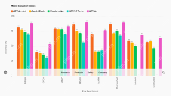 AV Byte: OpenAI's GPT-4o Mini and Other AI InnovationsApr 19, 2025 am 11:30 AM
This week's AI landscape exploded with groundbreaking releases from industry giants like OpenAI, Mistral AI, NVIDIA, DeepSeek, and Hugging Face. These new models promise increased power, affordability, and accessibility, fueled by advancements in tr
 Perplexity's Android App Is Infested With Security Flaws, Report FindsApr 19, 2025 am 11:24 AM
But the company’s Android app, which offers not only search capabilities but also acts as an AI assistant, is riddled with a host of security issues that could expose its users to data theft, account takeovers and impersonation attacks from malicious
 Everyone's Getting Better At Using AI: Thoughts On Vibe CodingApr 19, 2025 am 11:17 AM
You can look at what’s happening in conferences and at trade shows. You can ask engineers what they’re doing, or consult with a CEO. Everywhere you look, things are changing at breakneck speed. Engineers, and Non-Engineers What’s the difference be
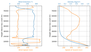 Rocket Launch Simulation and Analysis using RocketPy - Analytics VidhyaApr 19, 2025 am 11:12 AM
Simulate Rocket Launches with RocketPy: A Comprehensive Guide This article guides you through simulating high-power rocket launches using RocketPy, a powerful Python library. We'll cover everything from defining rocket components to analyzing simula


Hot AI Tools

Undresser.AI Undress
AI-powered app for creating realistic nude photos

AI Clothes Remover
Online AI tool for removing clothes from photos.

Undress AI Tool
Undress images for free

Clothoff.io
AI clothes remover

AI Hentai Generator
Generate AI Hentai for free.

Hot Article
Hot Tools

SecLists
SecLists is the ultimate security tester's companion. It is a collection of various types of lists that are frequently used during security assessments, all in one place. SecLists helps make security testing more efficient and productive by conveniently providing all the lists a security tester might need. List types include usernames, passwords, URLs, fuzzing payloads, sensitive data patterns, web shells, and more. The tester can simply pull this repository onto a new test machine and he will have access to every type of list he needs.

WebStorm Mac version
Useful JavaScript development tools

ZendStudio 13.5.1 Mac
Powerful PHP integrated development environment

Safe Exam Browser
Safe Exam Browser is a secure browser environment for taking online exams securely. This software turns any computer into a secure workstation. It controls access to any utility and prevents students from using unauthorized resources.

MinGW - Minimalist GNU for Windows
This project is in the process of being migrated to osdn.net/projects/mingw, you can continue to follow us there. MinGW: A native Windows port of the GNU Compiler Collection (GCC), freely distributable import libraries and header files for building native Windows applications; includes extensions to the MSVC runtime to support C99 functionality. All MinGW software can run on 64-bit Windows platforms.

