

 Technology peripheralsAIHave you really mastered coordinate system conversion? Multi-sensor issues that are inseparable from autonomous driving
Have you really mastered coordinate system conversion? Multi-sensor issues that are inseparable from autonomous driving

First Introduction and Key Points
This article mainly introduces several commonly used coordinate systems in autonomous driving technology, and how they Complete the association and transformation, and finally build a unified environment model. The focus here is to understand the conversion from vehicle to camera rigid body (external parameters), camera to image conversion (internal parameters), and image to pixel unit conversion. The conversion from 3D to 2D will have corresponding distortion, translation, etc.
Key points: Self-vehicle coordinate systemCamera body coordinate systemWhat needs to be rewritten is: Plane coordinate systemPixel coordinate system Difficulty: Required Considering image distortion, distortion removal and distortion are compensated on the image plane
II Introduction
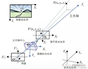
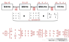
The visual system has a total of four coordinate systems: pixel plane coordinate system ( u,v), image coordinate system (x,y), camera coordinate system () and world coordinate system (). There is a connection between each coordinate system, so how to locate the coordinates of the world coordinate system through the image pixel coordinates needs to be solved through camera calibration. The key algorithm part lies in the coordinate system conversion, and the transformation needs to be completed through the representation of homogeneous coordinates.
Three sensor coordinate systems3.1 Camera coordinate system
The function of the camera is to
The shape and color information are compressed into a two-dimensional image. The camera-based perception algorithm extracts and restores elements and information in the three-dimensional world from two-dimensional images, such as lane lines, vehicles, pedestrians, etc., and calculates their relative positions to themselves. The coordinate systems related to the perception algorithm and the camera include the image coordinate system (pixel coordinate system) and the camera coordinate system. What needs to be rewritten is: the plane coordinate system
3.1.1 Image coordinate system (or pixel coordinate system) For photos or images stored on the computer, the upper left corner is generally the origin, with the positive x direction to the right and y downward. In the positive direction, the most commonly used unit is "pixel". The image coordinate system is a two-dimensional coordinate system, labeled (Xv, Yv).
The content that needs to be rewritten is: 3.1.2 Camera coordinate systemBecause the x-axis of the image coordinate system is to the right and the y-axis is to the right , so the camera coordinate system takes the center of the main optical axis of the lens as its origin. Generally speaking, the positive direction is the x-axis to the right, the positive direction is the y-axis downward, and the positive direction is the z-axis forward. In this way, the x and y directions are consistent with the direction of the image coordinate system, and the z direction represents the depth of field. The camera coordinate system can be expressed as (Xc, Yc)
What needs to be rewritten is: 3.1.3 What needs to be rewritten is: plane coordinate system (or imaging coordinate system)In order to
quantitatively describe the mapping relationship between three-dimensional space and two-dimensional image, what needs to be rewritten is introduced in graphics: the plane coordinate system. It is a translation of the camera coordinate system. The center is still on the main optical axis of the camera. The distance from the center of the optical axis is equal to the focal length of the camera We know that the camera will be behind the center of the optical axis A reduced inverted image appears on the film, which is the real image plane (Xf, Yf). However, for the convenience of analysis and calculation, we will set up a virtual image plane in front of the center of the optical axis. The image on the virtual image plane is an upright image, and the size is the same as the real inverted image
 What needs to be rewritten is: the plane coordinate system
Depending on the specific situation, any object can be represented, which is introduced by the camera. The unit is meters
 world coordinate system
, camera coordinate system , imaging coordinate system and pixel coordinates System
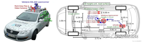
Four Lidar coordinate systemLidar (Light Detection and Ranging) is a
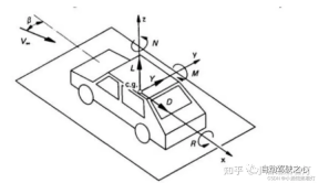
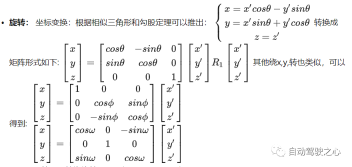
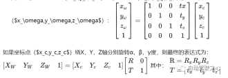
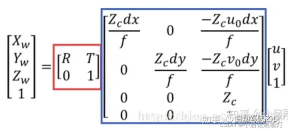
remote sensing technology that uses laser beams to measure objects distance. It emits rays with 360-degree rotation, and forms electric clouds based on different reflections of different target reflectivities. In the fields of autonomous driving and robotics, Lidar is often used as a main sensor to obtain 3D information about the surrounding environment. In most cases, the Lidar coordinate system is right-handed, but the specific definition may vary depending on the Lidar manufacturer. X axis: usually points in front of the Lidar. When the laser beam is fired directly forward, the distance measurement from that direction produces a positive value on the X-axis. Y axis: Usually points to the left side of the Lidar. When the laser beam is fired directly to the left, the distance measurement from that direction produces a positive value on the Y-axis. Z axis: Usually points above the Lidar, perpendicular to the X and Y axes. Height measurements are usually taken along the Z-axis, with positive values representing the object being higher than the Lidar device, and negative values representing it being lower than the Lidar device. describe the position of the sensor and object, this coordinate The system is called the world coordinate system; the self-car coordinate system generally refers to the center of the rear axle of the car body as the origin (because the center of the rear axle will not change relative to the swing of the car) , left front up or right front In the spatial coordinate system on the top, left (right) is generally horizontal, front is generally vertical, and top refers to the space above the ground. The coordinate system moves with the movement of the car. All downstream targets that need to be sensed and output must be under the own vehicle coordinate system, and the BEV perspective target also refers to under this coordinate system position of the object, and uses the rotation angle around these three orthogonal axes (roll angle, pitch angle, yaw angle) represents the attitude of the object. The time coordinate system has only one dimension. For convenience of expression, we generally discuss space coordinates and time coordinates separately. camera main point, camera focal length, and distortion coefficient . Internal parameters are generally given by the merchant, and camera calibration can also be performed. In autonomous driving applications, the internal parameters of the camera are constants and will not change during use, but they need to be calibrated before use. The shooting process of the camera can be abstracted into the process of mapping from the three-dimensional camera coordinate system to the two-dimensional coordinate system: the plane coordinate system, and then mapping to the image coordinate system. Generally, the internal parameters of the camera can be represented by a matrix: This matrix is usually called the internal parameter matrix or camera matrix. Infer the position of the object in the three-dimensional camera coordinate system through the two-dimensional image, such as obtaining distance and depth information. Obtain three-dimensional distance information from a two-dimensional image. If need to obtain the position of the object in the world coordinate system, you also need to know the pose of the camera in the world coordinate system. . This pose representation is called the external parameter of the camera, referred to as the external parameter, and is used to determine the relative positional relationship between the camera coordinates and the world coordinate system. In autonomous driving applications, obtaining this positional relationship requires a series of calibration and positioning work. The camera rotates and translates the matrix relative to other coordinate systems. The rotation external parameter is the Euler angle [yaw, patch, roll] mentioned above. The rotation order is generally (z-y-x), unit degree; the translation external parameter is the translation distance from the camera to the target coordinate system. , unit meter Relationship and conversion: - Since the vehicle moves in the world, the relationship between the self-vehicle coordinate system and the world coordinate system is time changing. - In order to convert between these two coordinate systems, a transformation matrix or transformation (usually consisting of a rotation and a translation) is usually required. This conversion can be obtained through various sensors (such as GPS, IMU, lidar) and algorithms (such as SLAM). - The transformation can be expressed as a 4x4 homogeneous coordinate matrix, allowing us to transform from one coordinate system to another. In most cases, the self-vehicle coordinate system and the world coordinate system are the same, and this is how this article understands The coordinate system transformation between objects can represent the rotation transformation addition of the coordinate system Up translation transformation, the conversion relationship from the world coordinate system to the camera coordinate system is also the same. Rotating different angles around different axes results in different rotation matrices. Schematic diagram of rotating θ around the Z axis: 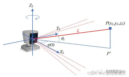
4.1 Definition
4.2 Importance
Five self-vehicle coordinate system
Choose a reference coordinate system in the general environment to 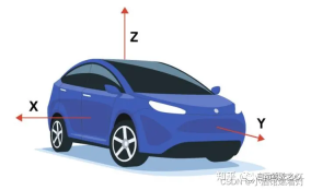
Intrinsic and extrinsic parameters of the six cameras
6.1 Internal parameters of the camera
Internal parameters are used to determine the transformation of the camera from three-dimensional space to two-dimensional space. Projection relationship of dimensional images. It mainly contains three parameters, 6.2 Focal length (f)
It describes the distance between the image
6.3 Principal point
It is a point in the image, usually close to the center of the image. It is the 2D point corresponding to a point in 3D space when projected onto the image plane.
6.4 Distortion coefficient
The lens of a real camera may introduce distortion, causing image distortion. Common distortions include radial distortion and tangential distortion.
 #
#6.5 Camera external parameters
Seven vehicle coordinate system and world coordinate system
7.1 Vehicle Coordinate System
7.2 World Coordinate System
Conversion between eight coordinate systems Relationship
8.1 From the world coordinate system to the camera coordinate system
8.2 Camera coordinate system to image coordinate system
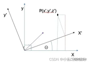
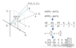
From the camera coordinate system to the image coordinate system, it belongs to the perspective projection relationship, converting from 3D to 2D. It can also be viewed as a change model of the pinhole model. Satisfy the triangle similarity theorem.
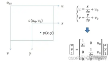
8.3 Image coordinate system to pixel coordinate system
In this case, unlike the previous coordinate system transformation, this There is no rotation transformation, but the position and size of the coordinate origin are inconsistent, so it is necessary to design telescopic transformation and translation transformation
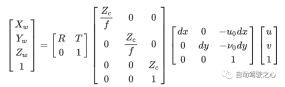
8.4 The relationship between the four coordinate systems
Nine Summary
It sorted out the various coordinate systems of autonomous driving and showed the differences between the various coordinate systems of autonomous driving. relationship, and finally obtain the conversion relationship between the pixel coordinate system and the world coordinate system.

The above is the detailed content of Have you really mastered coordinate system conversion? Multi-sensor issues that are inseparable from autonomous driving. For more information, please follow other related articles on the PHP Chinese website!

 Tool Calling in LLMsApr 14, 2025 am 11:28 AM
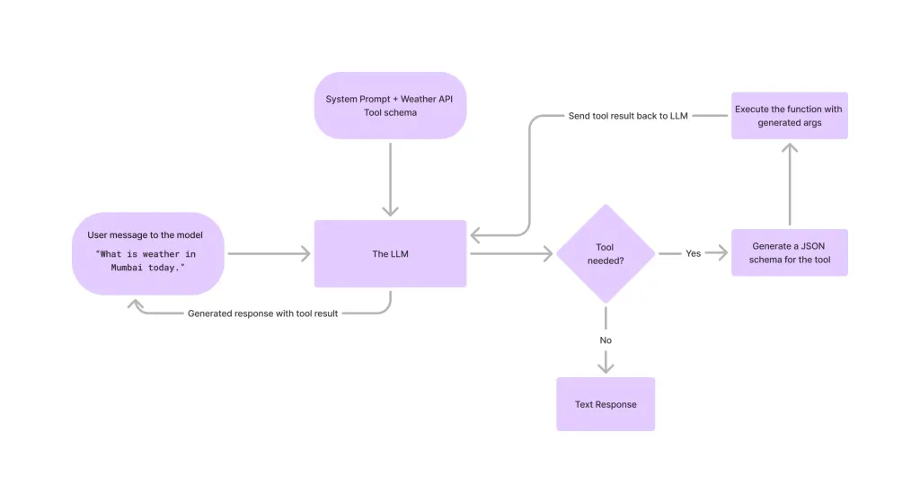
Large language models (LLMs) have surged in popularity, with the tool-calling feature dramatically expanding their capabilities beyond simple text generation. Now, LLMs can handle complex automation tasks such as dynamic UI creation and autonomous a
 How ADHD Games, Health Tools & AI Chatbots Are Transforming Global HealthApr 14, 2025 am 11:27 AM
Can a video game ease anxiety, build focus, or support a child with ADHD? As healthcare challenges surge globally — especially among youth — innovators are turning to an unlikely tool: video games. Now one of the world’s largest entertainment indus
 UN Input On AI: Winners, Losers, And OpportunitiesApr 14, 2025 am 11:25 AM
“History has shown that while technological progress drives economic growth, it does not on its own ensure equitable income distribution or promote inclusive human development,” writes Rebeca Grynspan, Secretary-General of UNCTAD, in the preamble.
 Learning Negotiation Skills Via Generative AIApr 14, 2025 am 11:23 AM
Easy-peasy, use generative AI as your negotiation tutor and sparring partner. Let’s talk about it. This analysis of an innovative AI breakthrough is part of my ongoing Forbes column coverage on the latest in AI, including identifying and explaining
 TED Reveals From OpenAI, Google, Meta Heads To Court, Selfie With MyselfApr 14, 2025 am 11:22 AM
The TED2025 Conference, held in Vancouver, wrapped its 36th edition yesterday, April 11. It featured 80 speakers from more than 60 countries, including Sam Altman, Eric Schmidt, and Palmer Luckey. TED’s theme, “humanity reimagined,” was tailor made
 Joseph Stiglitz Warns Of The Looming Inequality Amid AI Monopoly PowerApr 14, 2025 am 11:21 AM
Joseph Stiglitz is renowned economist and recipient of the Nobel Prize in Economics in 2001. Stiglitz posits that AI can worsen existing inequalities and consolidated power in the hands of a few dominant corporations, ultimately undermining economic
 What is Graph Database?Apr 14, 2025 am 11:19 AM
Graph Databases: Revolutionizing Data Management Through Relationships As data expands and its characteristics evolve across various fields, graph databases are emerging as transformative solutions for managing interconnected data. Unlike traditional
 LLM Routing: Strategies, Techniques, and Python ImplementationApr 14, 2025 am 11:14 AM
Large Language Model (LLM) Routing: Optimizing Performance Through Intelligent Task Distribution The rapidly evolving landscape of LLMs presents a diverse range of models, each with unique strengths and weaknesses. Some excel at creative content gen


Hot AI Tools

Undresser.AI Undress
AI-powered app for creating realistic nude photos

AI Clothes Remover
Online AI tool for removing clothes from photos.

Undress AI Tool
Undress images for free

Clothoff.io
AI clothes remover

AI Hentai Generator
Generate AI Hentai for free.

Hot Article
Hot Tools

SublimeText3 Mac version
God-level code editing software (SublimeText3)

Safe Exam Browser
Safe Exam Browser is a secure browser environment for taking online exams securely. This software turns any computer into a secure workstation. It controls access to any utility and prevents students from using unauthorized resources.

MantisBT
Mantis is an easy-to-deploy web-based defect tracking tool designed to aid in product defect tracking. It requires PHP, MySQL and a web server. Check out our demo and hosting services.

SecLists
SecLists is the ultimate security tester's companion. It is a collection of various types of lists that are frequently used during security assessments, all in one place. SecLists helps make security testing more efficient and productive by conveniently providing all the lists a security tester might need. List types include usernames, passwords, URLs, fuzzing payloads, sensitive data patterns, web shells, and more. The tester can simply pull this repository onto a new test machine and he will have access to every type of list he needs.

ZendStudio 13.5.1 Mac
Powerful PHP integrated development environment

