
 Technology peripheralsAIMicrosoft patent proposes monitoring light source solution for AR/VR light projection calibration interference
Microsoft patent proposes monitoring light source solution for AR/VR light projection calibration interference

(Nweon August 24, 2023) XR equipment usually includes a left projector coupled to the left beam path and a right projector coupled to the right beam path. The left projector is configured to generate a left image and then propagate the left image through the left beam path to the user's left eye. The correct projector is configured to generate the correct image, which then travels through the correct beam path to the user's right eye.
The construction of this XR device may change due to regular use, temperature changes, and/or shock. When the structure of the R device changes, the image may lose its visual axis and become incorrectly aligned. This problem may become severe in glasses-shaped devices.
There are XR devices configured to project a calibration image and use the calibration image to determine if the monitor is positioned correctly. Since the calibration image is visible to the user, the user experience is often disrupted by calibration/correction operations.
In the patent application titled "Monitoring position and orientation of a projector", Microsoft proposed to use a monitoring light source (such as a laser diode or laser diode array) to generate a monitoring beam to monitor the position and direction of the projector, thereby solving the above problems .
The projector has a reflective spatial light modulator. The surveillance beam is directed into the surveillance camera to obtain direct feedback, which can then be used to correct for changes in axial view of the XR device. In one embodiment, a single camera is configured to combine images from the left and right eye projectors and reduce errors in this measurement.
In one embodiment, the monitor light source may be one or more edge emitter diodes or one or more vertical external cavity surface emitting laser VECSEL diodes with a very narrow wavelength band. In one embodiment, the monitor light source is a set of edge emitter diodes or VECSEL diodes configured to project a set of points.
It is advantageous to use a laser beam with a very narrow wavelength band as a monitoring beam, because such a laser wavelength band can be selected to be invisible to the user, or different from the illumination beam (visible beam), so that the monitoring beam can be removed from the illumination beam Filter out. In addition, the laser optical power can be set to be greater than the illumination light itself, thereby overcoming the signal-to-noise ratio problem of surveillance cameras. At the same time, such a narrow wavelength band can be used for very compact surveillance cameras based on phase lenses.
In one embodiment, the monitor beam is modulated by a reflective spatial light modulator of the projector before propagating through the monitor beam path to produce the monitor image. Alternatively, the monitor beam is not modulated by the projector's reflective spatial light modulator before propagating through the monitor beam path to generate a monitor image, and the monitor camera may include a quadrant diode detector, camera and/or lensless camera.
In one embodiment, the monitor beam is directed to a different path in the beam path than the projector, which further improves signal versus noise at the monitor camera. Additionally, a dedicated beam path for the monitor signal that is separate from the projector signal provides the end user with laser safety because there is no path to point it towards the user's eyes.
The surveillance camera can measure the pose of the left and right images or changes in both images and monitor the applied corrections. Projectors are available in a number of different projector designs. The integration of the monitoring beam and the illumination beam may come from the same side, or may come from different sides and be combined by a beam combiner, for example a dichroic beam combiner.

Figure 1A illustrates an example architecture of a projection system 100A that implements the principles described herein. The projection system 100A includes an illumination light source 110 , a monitor light source 120 and a projector 140 . The illumination light source 110 is configured to emit an illumination beam 112A to the projector 140 , and the monitoring light source 120 is configured to emit a monitoring beam 122A to the projector 140 .
In one embodiment, projector 140 includes reflective spatial light modulator 142 configured to modulate beams 112A and 122A to produce output 144A of projector 140 . The output 144A of the projector 140 is a projected combined beam 144A, which includes a projected illumination beam 1441 and a projected monitoring beam 144M.
Subsequently, the projected illumination beam 1441 is directed to the illumination beam path 152 directed to the user's eye 160, so that the user's eye 160 sees the display image corresponding to the illumination beam 112A.
The projected monitoring beam 144M is directed to the monitoring camera 170, so that the monitoring camera 170 captures a monitoring image corresponding to the monitoring beam 122A.
Since both the illumination beam 112A and the monitoring beam 122A are projected through the projector 140, the monitoring image captured by the monitoring camera 170 can be used to determine the direction or position of the monitoring image.
In one embodiment, the illumination light source 110 is configured to emit a light beam of a first wavelength band, such as a visible red, green, and blue (RGB) light beam, including a red light beam, a green light beam, a blue light beam, or a combination thereof. The monitoring light source 120 is configured to emit a light beam of a second wavelength band, such as invisible light, so that the image generated by the monitoring light source is detectable only to the monitoring camera 170 but is invisible to human eyes.
In one embodiment, the illumination beam path 152 is configured to propagate light in a first wavelength band, and the monitor beam path 154 is configured to propagate light in a second wavelength band. In this way, the projected combined beam 144A is split into the illumination beam path 152 and the monitoring beam path 154 .
In one embodiment, a filter is disposed before the illumination beam path 152 to filter out the beam of the second wavelength, so that only the beam of the first wavelength band propagates on the illumination beam path 152 . In addition, a filter is disposed before the monitor beam path 154 to filter out the beam of the first wavelength, so that only the monitor beam in the second wavelength band propagates on the monitor beam path 154 .
Since the surveillance beam 112A is directed on a different path than the illumination beam, it further improves the signal-to-noise ratio at the surveillance camera 170 . In one embodiment, the power of the monitoring beam is greater than the power of the illuminating beam, so that the signal-to-noise ratio is further improved to allow the monitoring image to be recognized at the camera 170 .
In one embodiment, the illumination light source 110 is configured to emit an illumination beam in a first direction, and the monitoring light source 120 is configured to emit a monitoring beam in a second direction intersecting the first direction. The illumination beam and the monitoring beam intersect at a first position of the projector and are output at two independent positions of the projector, namely a second position and a third position.
The output beam then propagates in different directions. The projected illumination beam travels in a first direction toward the user's eyes, and the projected monitor beam travels in a second direction toward the monitor camera.
Alternatively, in one embodiment, a beam combiner may be used to combine the illumination light and the monitor light into a combined beam directed toward the projector 140 .

Figure 1B shows an example structure of projection system 100B. The projection system 100B includes a beam combiner 130 configured to combine the illumination light 112B and the monitoring beam 122B into a combined beam 132 directed toward the projector 140 . The projector 140 is configured to project the combined beam 132 into the projected combined beam 144B. Similar to the projected combined beam 144A in Figure 1A, the projected combined beam 144B is split and propagated on two different beam paths 152, 154.
The projection system 100A or 100B as shown in Figure 1A or 1B can be implemented in a portable projector and/or a head-mounted device (such as a VR/AR device), allowing the portable projector and/or head-mounted device to self- Monitor and/or adjust its axial alignment. It is worth noting that when implemented in a head-mounted device, two such projection systems can be implemented, one for the left eye and another for the right eye.

Figures 2A and 2B illustrate front and top views of an example head mounted device 200 implementing a left projection system 200L and a right projection system 200R, each corresponding to the projection system 100A or 100B of Figure 1A or 1B . As shown, left projection system 200L includes illumination light source 210L and monitoring light source 220. In one embodiment, left projection system 200L also includes a beam combiner 230L.

Referring to Figure 2B, the illumination light source 210L is configured to emit an illumination beam 212L, and the monitoring light source 220L is configured to emit a monitoring beam 222L. The beam combiner 230L is configured to combine the illumination beam 212L and the monitoring beam 222L into a combined beam 232L, which is then projected into a projection combined beam 242L by the projector 240L.
Referring to Figure 2A, the head mounted device 200 includes both an illumination beam path 252L (corresponding to the illumination beam path 152 of Figure 1A or 1B) and a monitoring beam path 254L (corresponding to the monitoring beam path 154 of Figure 1A or 1B).
The first portion of the projected combined beam propagates toward the user's eye (not shown) through illumination beam path 252L, and the second portion of the projected combined beam propagates toward the camera 270 through the monitor beam path 254L .
The first portion of the projected combined beam includes at least a portion of the illumination beam projected by the projector 240L, allowing the user's eyes to see a display image corresponding to the illumination beam. The second portion of the projected combined beam includes at least a portion of the first monitor beam projected by the projector 240L.
Referring again to Figure 2B, the two monitoring beam paths 254L and 256L include a beam combiner 260 configured to combine the two monitoring beams into a combined monitoring beam 262. The combined surveillance beam 262 is then propagated into the surveillance camera 270.
The surveillance camera 270 is configured to receive the second part of the projected combined beam and capture a surveillance image corresponding to the surveillance beam projected by the projector 240L.
Then, the monitor image is analyzed to determine the orientation or position of the monitor image. In the event that the monitor image orientation or position is determined to be incorrect, adjust the orientation or position of projector 240L. For example, in one embodiment, image data associated with the illumination image is transformed such that the illumination image is rotated by a specific angle based on the orientation of the monitor image.
As another example, image data associated with the illumination image may be transformed to cause the illumination image to move, enlarge, and/or reduce.
In one embodiment, the illumination light source 210L is configured to emit a light beam of a first wavelength band, such as visible light, and the monitoring light source 220L is configured to emit a light beam of a second wavelength band, such as invisible light, such that the image generated by the monitoring light source Visible only to the surveillance camera 270 and not to the user.
In one embodiment, the power of the monitoring beam is greater than the power of the illumination beam, so that the monitoring image captured by the monitoring camera 270 has a sufficient signal-to-noise ratio to allow identification of the monitoring image.
In one embodiment, the illumination beam path 252L is configured to propagate light in a first wavelength band and the monitor beam path 254L is configured to propagate light in a second wavelength band. Therefore, the projected combined beam is divided into an illumination beam path 252L and a monitoring beam path 254L.
In one embodiment, a filter is disposed before the illumination beam path 252L to filter out the beam of the second wavelength, so that only the beam of the first wavelength band propagates on the illumination beam path 252L. In addition, a filter is disposed before the monitor beam path 254L to filter out the beam of the first wavelength, so that only the monitor beam in the second wavelength band propagates on the monitor beam path 254L.

In one embodiment, the monitor image includes a predetermined set of points or lines. 3A and 3B illustrate examples of surveillance images captured by the surveillance camera 270.
As shown in Figure 3A, the monitoring image 300A includes a grid composed of four points 302A, 304A, 306A, 308A. The grid can be configured by filtering out the light beam in the first wavelength band and/or using This is accomplished by monitoring beam path 254L that propagates a beam in the second wavelength band.
In one embodiment, the surveillance image 300A is compared with the axial view 310A of the surveillance camera 270 to determine whether the surveillance image 330A is correctly oriented or positioned.
As shown in Figure 3B, the monitoring image 300B includes a grid composed of four points 302B, 304B, 306B, 308B superimposed on the display image 320B, which can be achieved by not filtering out the light beam in the first wavelength band, or Caused using a beam path configured to propagate a beam in a first wavelength band and a second wavelength band.
Additionally, the surveillance image 300B may be compared with the inner diameter 310B of the surveillance camera 270 to determine whether the surveillance image 300B is correctly oriented or positioned. In one embodiment, the power of the monitoring beams 222L, 222R is greater (or significantly greater) than the power of the illumination beams 212L, 212R, thereby further increasing the signal-to-noise ratio to allow identification of the surveillance image.
Returning to Figures 2A-2B, the head mounted device 200 simultaneously includes a second illumination light source 210R, a second monitor light source 220R, a second beam combiner 230R, a second illumination beam path 252R, and a second monitor beam. Path 254R, first monitor light source 220L, first beam combiner 230L, first illumination beam path 252L, and first monitor beam path 254L. The first group of elements 210L, 220L, 230L, 240L and the second group of elements 210R, 220R, 230R, 240R are symmetrically arranged on the left and right sides of the head mounted device 200.
The first set of components 210L, 220L, 230L, 240L are configured to project the first image on the user's first eye, and the second set of components 210R, 220R, 230R, 240R are configured to project on the user's second eye Project a second image.
In one embodiment, surveillance camera 270 is configured to receive a portion of a first projected combined beam from first surveillance beam path 254L and/or a portion of a second projected combined beam from second surveillance beam path 254R. The surveillance camera 270 is configured to capture a first surveillance image based on a first light beam received from the first surveillance beam path 254L, and/or to capture a first surveillance image based on a second light beam received from the second surveillance beam path 254R. 2. Surveillance images.
In one embodiment, the first surveillance image or the second surveillance image are analyzed respectively to determine whether each of the first surveillance image or the second surveillance image is correctly oriented or positioned. The surveillance camera 270 is configured to capture the first surveillance image and the second surveillance image that overlap each other. The first monitor image is compared to the second monitor image to determine whether the relative endovision of the two eyes is aligned.
In one embodiment, a separate surveillance camera is implemented for each projection system. For example, the head mounted device includes a first surveillance camera configured to capture a first surveillance image from a first projector, and a second surveillance camera configured to capture a second surveillance image from a second projector. The captured first and second surveillance images may then be compared to the respective inner diameters of the first and second cameras, or to each other to determine the relative inner diameters of each other.

Figures 4A and 4B illustrate examples of images 400A, 400B captured by surveillance camera 270, where a first surveillance image (received from first surveillance beam path 254L) and a second surveillance image (received from second surveillance beam path 254R receive) superimposed on each other.
As shown in Figure 4A, the image 400A captured by the surveillance camera 270 includes a first surveillance image of a first grid having four points 402A, 404A, 406A, and 408A. The second monitor image has a second grid consisting of four points 412A, 414A, 416A, 418A. The first monitoring image and the second monitoring image are superimposed on each other.
As shown in Figure 4A, the first grid points 402A, 404A, 406A, and 408A are not aligned with the second grid points 412A, 414A, 416A, and 418A, indicating that they are not aligned with the relative visual axes of the two eyes.
In one embodiment, to determine the relative axial misalignment of the two eyes, the head mounted device 200 is configured to adjust the first projector or the second projector (or the first illumination image and/or the second The direction or position of at least one of the illumination images) so that the relative axis is aligned.
Figure 4B shows an example of an image 400B captured by the surveillance camera 270, including a first display image 410B, a first surveillance image of a first grid with four points 402B, 404B, 406B, 408B, a second display Image 420B and a second surveillance image of a second grid of four points 412B, 414B, 416B, 418B.
The first display image 410B, the first monitoring image, the second display image 420B, and the second monitoring image are superimposed on each other. In one embodiment, the overlay image 400B is further processed to extract the first surveillance image and/or the second surveillance image. The extracted first surveillance image and/or second surveillance image is then analyzed to determine whether the surveillance image and/or second surveillance image is correctly oriented or positioned.

Figure 8 shows a flow diagram of an example method 800 implemented on a head mounted device. The method 800 includes capturing a first surveillance image from a first projector (act 810) and capturing a second surveillance image from a second projector (act 820).
act810, obtaining the first monitor image from the first projector is performed by a first projection system, and the projection system includes a first illumination light source, a first monitor light source, a first beam path, a second beam path and a camera.
act810, emitting a first illumination beam from a first illumination light source (Act 710), emitting a first monitoring light beam from a first monitoring light source (Act 720), and projecting the illumination beam and the monitoring beam to a first projector through a first projector in a projected beam. In one embodiment, the first illumination light source and the first monitor light source are configured to emit light in different directions of interest to each other, and the first illumination light beam and the first monitor light beam are combined into a third light beam directed toward the first projector. A combination of beams.
act810 simultaneously includes propagating a first portion of the first projected combined beam toward the user's first eye through a first beam path, and propagating a second portion of the second projected beam toward the camera through the second beam path, and then through the camera Capture surveillance images.
act820, Similarly, capturing the second monitor image from the second projector is performed by a second projection system, and the projection system includes a second illumination light source, a second monitor light source, a third beam path, and a fourth beam path and camera.
In one embodiment, the first projection system and the second projection system share the same camera. The first projection system includes a first camera, and the second projection system includes a second camera. The first surveillance image and the second surveillance image are captured superimposed on each other. In one embodiment, the first surveillance image and the second surveillance image are captured separately.
act830, then, the first monitoring image and the second monitoring image are compared with each other to determine whether the relative inner views of the first projector and the second projector are aligned with each other.
act840, in response to determining a relative axis misalignment, adjusting the orientation or position of at least one of the first or second projectors. In one embodiment, in response to determining whether the relative axial views are aligned, the projection system may repeat actions 810-830 again at a predetermined time and/or at a predetermined frequency based on the user input.
In one embodiment, the illumination beam and the monitoring beam are not combined or parallel. The illumination beam and monitoring beam intersect inside the projector and come out at two independent locations. Such embodiments make it easy to send illumination beams to the user's eyes and surveillance beams to surveillance cameras.
Related Patents: Microsoft Patent | Monitoring position and orientation of a projector
The Microsoft patent application titled "Monitoring position and orientation of a projector" was originally submitted in January 2022 and was recently published by the US Patent and Trademark Office.
The above is the detailed content of Microsoft patent proposes monitoring light source solution for AR/VR light projection calibration interference. For more information, please follow other related articles on the PHP Chinese website!

 MarkItDown MCP Can Convert Any Document into Markdowns!Apr 27, 2025 am 09:47 AM
Handling documents is no longer just about opening files in your AI projects, it’s about transforming chaos into clarity. Docs such as PDFs, PowerPoints, and Word flood our workflows in every shape and size. Retrieving structured
 How to Use Google ADK for Building Agents? - Analytics VidhyaApr 27, 2025 am 09:42 AM
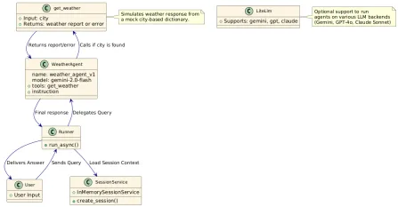
Harness the power of Google's Agent Development Kit (ADK) to create intelligent agents with real-world capabilities! This tutorial guides you through building conversational agents using ADK, supporting various language models like Gemini and GPT. W
 Use of SLM over LLM for Effective Problem Solving - Analytics VidhyaApr 27, 2025 am 09:27 AM
summary: Small Language Model (SLM) is designed for efficiency. They are better than the Large Language Model (LLM) in resource-deficient, real-time and privacy-sensitive environments. Best for focus-based tasks, especially where domain specificity, controllability, and interpretability are more important than general knowledge or creativity. SLMs are not a replacement for LLMs, but they are ideal when precision, speed and cost-effectiveness are critical. Technology helps us achieve more with fewer resources. It has always been a promoter, not a driver. From the steam engine era to the Internet bubble era, the power of technology lies in the extent to which it helps us solve problems. Artificial intelligence (AI) and more recently generative AI are no exception
 How to Use Google Gemini Models for Computer Vision Tasks? - Analytics VidhyaApr 27, 2025 am 09:26 AM
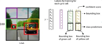
Harness the Power of Google Gemini for Computer Vision: A Comprehensive Guide Google Gemini, a leading AI chatbot, extends its capabilities beyond conversation to encompass powerful computer vision functionalities. This guide details how to utilize
 Gemini 2.0 Flash vs o4-mini: Can Google Do Better Than OpenAI?Apr 27, 2025 am 09:20 AM
The AI landscape of 2025 is electrifying with the arrival of Google's Gemini 2.0 Flash and OpenAI's o4-mini. These cutting-edge models, launched weeks apart, boast comparable advanced features and impressive benchmark scores. This in-depth compariso
 How to Generate and Edit Images Using OpenAI gpt-image-1 APIApr 27, 2025 am 09:16 AM
OpenAI's latest multimodal model, gpt-image-1, revolutionizes image generation within ChatGPT and via its API. This article explores its features, usage, and applications. Table of Contents Understanding gpt-image-1 Key Capabilities of gpt-image-1
 How to Perform Data Preprocessing Using Cleanlab? - Analytics VidhyaApr 27, 2025 am 09:15 AM
Data preprocessing is paramount for successful machine learning, yet real-world datasets often contain errors. Cleanlab offers an efficient solution, using its Python package to implement confident learning algorithms. It automates the detection and
 The AI Skills Gap Is Slowing Down Supply ChainsApr 26, 2025 am 11:13 AM
The term "AI-ready workforce" is frequently used, but what does it truly mean in the supply chain industry? According to Abe Eshkenazi, CEO of the Association for Supply Chain Management (ASCM), it signifies professionals capable of critic


Hot AI Tools

Undresser.AI Undress
AI-powered app for creating realistic nude photos

AI Clothes Remover
Online AI tool for removing clothes from photos.

Undress AI Tool
Undress images for free

Clothoff.io
AI clothes remover

Video Face Swap
Swap faces in any video effortlessly with our completely free AI face swap tool!

Hot Article
Hot Tools

Atom editor mac version download
The most popular open source editor

SAP NetWeaver Server Adapter for Eclipse
Integrate Eclipse with SAP NetWeaver application server.

Dreamweaver Mac version
Visual web development tools

VSCode Windows 64-bit Download
A free and powerful IDE editor launched by Microsoft

WebStorm Mac version
Useful JavaScript development tools

