


In-depth interpretation of smart car sensor calibration technology

Calibrating sensors is a necessary link in the autonomous driving perception system and a necessary step and prerequisite for subsequent sensor fusion. Its purpose is to transform two or more sensors into a unified spatio-temporal coordinate system so that sensor fusion can be achieved Having meaning is a key prerequisite for perceptual decision-making. Any sensor needs to be calibrated through experiments after manufacturing and installation to ensure that the sensor meets the design specifications and ensures the accuracy of the measurement values.
After the sensor is installed on the autonomous vehicle, it needs to be calibrated; at the same time, during the driving process of the vehicle, due to vibration and other reasons, the sensor position will deviate from the original position. , so it is necessary to calibrate the sensor at certain intervals. Self-driving cars work simultaneously through multiple types of sensors for environmental perception and self-awareness. The robustness and accuracy of sensors are particularly important in the perception process of self-driving cars.
01 Camera calibration
The vehicle-mounted camera is installed on the vehicle at a certain angle and position. In order to compare the environmental data collected by the vehicle-mounted camera with To correspond to real objects in the vehicle driving environment, that is, to find the conversion relationship between the point coordinates in the image pixel coordinate system generated by the vehicle camera and the point coordinates in the camera environment coordinate system, camera calibration is required.
1. Camera internal parameter calibration
1.1 Establishment of camera model
Through the mutual conversion relationship between the environment coordinate system, camera coordinate system, image physical coordinate system, and image pixel coordinate system, we can find the conversion relationship between the environment coordinate system and the image pixel coordinate system, that is,
Point P for the real world. Its coordinates in the environment coordinate system are (Xw, Yw, Zw), and its position in the image is (u, v). The two have the following relationship:

Conversion relationship between the environment coordinate system and the image pixel coordinate system
For the internal parameter matrix, the fourth constants fx, fy, Uo, Vo. It is related to the design technical indicators such as the focal length, main point and sensor of the camera, and has nothing to do with external factors (such as the surrounding environment, camera position), so it is called the internal parameter of the camera. The internal reference is determined when the camera leaves the factory. However, due to manufacturing process and other issues, even cameras produced on the same production line have slightly different internal parameters. Therefore, it is often necessary to determine the internal parameters of the camera through experiments. The calibration of a monocular camera usually refers to determining the internal parameters of the camera through experimental means.
The external parameter matrix includes the rotation matrix and the translation matrix. The rotation matrix and the translation matrix jointly describe how to convert the point from the world coordinate system to the camera coordinate system. In computer vision, the process of determining the external parameter matrix is usually called visual localization. After the on-board camera is installed in a self-driving car, the camera position needs to be calibrated in the vehicle coordinate system. In addition, due to the bumps and vibrations of the car, the position of the on-board camera will slowly change over time, so self-driving cars need to recalibrate the camera position regularly, a process called calibration.
1.2 Camera distortion correction
In actual use, the camera cannot completely accurately follow the ideal pinhole When the camera model performs perspective projection, there is usually lens distortion, that is, there is a certain optical distortion error between the image generated by the object point on the actual camera imaging plane and the ideal imaging. The distortion error is mainly radial distortion error and tangential distortion error. .
Radial distortion: Due to the characteristics of the lens, light tends to bend to a small or large extent at the edge of the camera lens, which is called radial distortion. This kind of distortion is more obvious in ordinary cheap lenses. Radial distortion mainly includes barrel distortion and pincushion distortion. Barrel distortion is a barrel-shaped expansion of the imaging image caused by the structure of the lens object and the lens group in the lens. Barrel distortion is usually easier to detect when using a wide-angle lens or when using the wide-angle end of a zoom lens. Pincushion distortion is the phenomenon of the image "shrinking" toward the center caused by the lens. People are more likely to notice pincushion distortion when using the telephoto end of a zoom lens.
- Tangential distortion: It is caused by the fact that the lens itself is not parallel to the camera sensor plane (imaging plane) or image plane. This situation is mostly caused by the lens being pasted to the lens mold. Caused by installation deviation on the group.
#In computer vision, radial distortion has a very important impact on scene reconstruction. The autonomous driving system's perception of the environment requires the camera to achieve high-precision reconstruction of the surrounding environment. If distortion is not corrected, accurate environmental information cannot be obtained. For example, targets in the environment may appear in any area of the image. If distortion is not corrected, the target location and size obtained through vision technology are often inaccurate, which will directly affect the driving safety of autonomous vehicles. In addition, self-driving cars are equipped with multiple cameras at different locations. If radial distortion is not considered, during the image stitching process, the blur effect of the stitched images will be caused by mismatching of corresponding features.
For general cameras, the radial distortion of the image is often described as a low-order polynomial model. Assume (u, v) is the coordinate of the corrected point, (u', u') is the coordinate of the uncorrected point, then the transformation between the two can be determined by the following formula:

Radial distortion low-order polynomial model
On the other hand, for the cut Tangential distortion can be corrected using the other two parameters p1 and p2:

Tangential distortion Low-order polynomial model
##1.3 Camera internal parameter calibration method
##At this stage, the calibration of distortion parameters is generally performed simultaneously with other internal parameters. The most widely used one at present is the Zhang Zhengyou calibration method proposed by Zhang Zhengyou in 2000. Zhang Zhengyou's calibration method finds the internal corner points of the chessboard calibration board in each image by photographing the chessboard calibration board at different positions, and establishes constraints on the matrix through the correspondence between the internal corner points. Thereby restoring the internal parameter matrix K. 
In self-driving cars, in order to minimize the perception blind area, a multi-camera mode is often used . Determining the relative positional relationship between multiple cameras is called the external parameter calibration of the camera.
From another perspective, the external parameter calibration of the camera can also be called the "pose estimation" problem. The relative pose [R|t] between the two cameras has 6 degrees of freedom (spatial position and rotation relationship). Theoretically, as long as the two cameras acquire 3 points in the space at the same time, the relationship between the two can be restored. relative posture. The problem of recovering the relative posture between cameras from three pairs of corresponding points is called the "Perspective-3-Point-Problem, P3P". In reality, more than 3 points are often used to restore the relative posture to improve robustness, and the P3P problem is generalized as a PnP problem.
Initially, researchers used the Direct Linear Transform (DLT) method to solve the PnP problem. Later, in order to improve the accuracy, the researchers proposed a robust linearization reprojection error. The generation selection method is used to solve the PnP problem, and the famous bundle adjustment method (Bundle Adjustment, BA) in attitude estimation is proposed.
02 Lidar calibration
Lidar is one of the main sensors of the autonomous driving platform and plays an important role in perception and positioning. Like cameras, lidar also needs to calibrate its internal and external parameters before use. Internal parameter calibration refers to the conversion relationship between its internal laser transmitter coordinate system and the radar's own coordinate system. It has been calibrated before leaving the factory and can be used directly. What the autonomous driving system needs to perform is external parameter calibration, that is, the relationship between the lidar's own coordinate system and the vehicle body coordinate system.The lidar and the vehicle body are rigidly connected, and the relative posture and displacement between the two are fixed. In order to establish the relative coordinate relationship between lidars and between lidars and vehicles, it is necessary to calibrate the lidar installation and convert the lidar data from the lidar coordinate system to the vehicle body coordinate system. 
##Car body coordinate system and lidar coordinate system

Through experiments, we collect the real coordinates of the same point in two coordinate systems, that is, the point with the same name, and establish a series of equations to calculate these 16 Unknown parameters. In addition, in autonomous vehicles, it is usually necessary to calibrate the laser radar and the inertial navigation unit (IMU) coordinate system to establish the relationship between the laser radar and the vehicle body coordinate system.
1. Calibration between LiDAR and LiDAR
For autonomous vehicles, sometimes there are multiple LiDARs In this case, each external environment acquired by lidar must be accurately mapped to the vehicle body coordinate system. Therefore, when there are multiple lidars, the relative positions of the multiple lidars need to be calibrated and calibrated.
There are many ideas for calibrating external parameters between lidars. The more commonly used one is to indirectly derive the relationship between lidars through the coordinate conversion relationship between different lidars and the car body. coordinate transformation relationship between them.
2. Calibration of lidar and camera
In an autonomous vehicle, the lidar and the driverless vehicle are rigidly connected. The relative attitude and displacement between them are fixed. Therefore, the data points obtained by lidar scanning have unique position coordinates corresponding to them in the environmental coordinate system. Similarly, the camera also has unique position coordinates in the environment coordinate system, so there is a fixed coordinate transformation between the lidar and the camera. The joint calibration of lidar and cameras is to complete the unification of multiple sensor coordinates such as single-line lidar coordinates, camera coordinates, and image pixel coordinates by extracting the corresponding feature points of the calibration object on the single-line lidar and image, and realize the lidar and camera spatial calibration.
After the camera external parameter calibration and lidar external parameter calibration are completed, the relationship between the two can actually be completely determined. The lidar scanning point can be projected to the image pixel coordinate system.
Same as the internal parameter calibration method of the camera, the external parameter calibration method of the lidar and camera can also use the calibration method of the calibration plate.
The above is the detailed content of In-depth interpretation of smart car sensor calibration technology. For more information, please follow other related articles on the PHP Chinese website!

 How to Run LLM Locally Using LM Studio? - Analytics VidhyaApr 19, 2025 am 11:38 AM
Running large language models at home with ease: LM Studio User Guide In recent years, advances in software and hardware have made it possible to run large language models (LLMs) on personal computers. LM Studio is an excellent tool to make this process easy and convenient. This article will dive into how to run LLM locally using LM Studio, covering key steps, potential challenges, and the benefits of having LLM locally. Whether you are a tech enthusiast or are curious about the latest AI technologies, this guide will provide valuable insights and practical tips. Let's get started! Overview Understand the basic requirements for running LLM locally. Set up LM Studi on your computer
 Guy Peri Helps Flavor McCormick's Future Through Data TransformationApr 19, 2025 am 11:35 AM
Guy Peri is McCormick’s Chief Information and Digital Officer. Though only seven months into his role, Peri is rapidly advancing a comprehensive transformation of the company’s digital capabilities. His career-long focus on data and analytics informs
 What is the Chain of Emotion in Prompt Engineering? - Analytics VidhyaApr 19, 2025 am 11:33 AM
Introduction Artificial intelligence (AI) is evolving to understand not just words, but also emotions, responding with a human touch. This sophisticated interaction is crucial in the rapidly advancing field of AI and natural language processing. Th
 12 Best AI Tools for Data Science Workflow - Analytics VidhyaApr 19, 2025 am 11:31 AM
Introduction In today's data-centric world, leveraging advanced AI technologies is crucial for businesses seeking a competitive edge and enhanced efficiency. A range of powerful tools empowers data scientists, analysts, and developers to build, depl
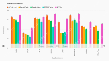 AV Byte: OpenAI's GPT-4o Mini and Other AI InnovationsApr 19, 2025 am 11:30 AM
This week's AI landscape exploded with groundbreaking releases from industry giants like OpenAI, Mistral AI, NVIDIA, DeepSeek, and Hugging Face. These new models promise increased power, affordability, and accessibility, fueled by advancements in tr
 Perplexity's Android App Is Infested With Security Flaws, Report FindsApr 19, 2025 am 11:24 AM
But the company’s Android app, which offers not only search capabilities but also acts as an AI assistant, is riddled with a host of security issues that could expose its users to data theft, account takeovers and impersonation attacks from malicious
 Everyone's Getting Better At Using AI: Thoughts On Vibe CodingApr 19, 2025 am 11:17 AM
You can look at what’s happening in conferences and at trade shows. You can ask engineers what they’re doing, or consult with a CEO. Everywhere you look, things are changing at breakneck speed. Engineers, and Non-Engineers What’s the difference be
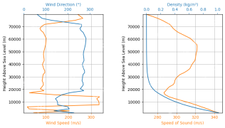 Rocket Launch Simulation and Analysis using RocketPy - Analytics VidhyaApr 19, 2025 am 11:12 AM
Simulate Rocket Launches with RocketPy: A Comprehensive Guide This article guides you through simulating high-power rocket launches using RocketPy, a powerful Python library. We'll cover everything from defining rocket components to analyzing simula


Hot AI Tools

Undresser.AI Undress
AI-powered app for creating realistic nude photos

AI Clothes Remover
Online AI tool for removing clothes from photos.

Undress AI Tool
Undress images for free

Clothoff.io
AI clothes remover

Video Face Swap
Swap faces in any video effortlessly with our completely free AI face swap tool!

Hot Article
Hot Tools

SublimeText3 Linux new version
SublimeText3 Linux latest version

Dreamweaver Mac version
Visual web development tools
ZendStudio 13.5.1 Mac
Powerful PHP integrated development environment

SecLists
SecLists is the ultimate security tester's companion. It is a collection of various types of lists that are frequently used during security assessments, all in one place. SecLists helps make security testing more efficient and productive by conveniently providing all the lists a security tester might need. List types include usernames, passwords, URLs, fuzzing payloads, sensitive data patterns, web shells, and more. The tester can simply pull this repository onto a new test machine and he will have access to every type of list he needs.

SublimeText3 Mac version
God-level code editing software (SublimeText3)

