In the system development process, the flow chart is a design tool used specifically in the design stage; the program flow chart is independent of any programming language, relatively intuitive, clear, and easy to learn and master.

#The operating environment of this article: Windows 10 system, Dell G3 computer.
In what stage of the system development process is flow chart a tool used?
Program flow chart is a design tool specific to the design stage.
Program flow chart is independent of any programming language, relatively intuitive, clear, and easy to learn and master.
Related introduction:
1. N-S diagram, Nassi and Shneiderman proposed a graphical description tool that conforms to the principles of structured programming, called a box diagram, also called an N-S diagram. In order to represent the five basic control structures, five graphic components are specified in the N-S diagram.
2. DFD diagram, referred to as DFD, graphically expresses the logical functions of the system, the logical flow of data within the system, and the logical transformation process from the perspective of data transmission and processing. It is a structured system analysis method. The main expression tool and a graphical method used to represent software models.
3. PAD diagram, PAD is the abbreviation of Problem Analysis Diagram. It is a graphical tool proposed by Hitachi Corporation of Japan and evolved from the program flow chart. It uses structured programming ideas to express the logical structure of the program.
For more related knowledge, please visit the FAQ column!
The above is the detailed content of What stage is a flow chart used as a tool in the system development process?. For more information, please follow other related articles on the PHP Chinese website!
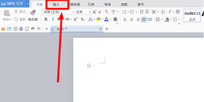 WPS文档怎么画流程图Mar 20, 2024 pm 10:20 PM
在我们工作会议中,经常会用到流程图,流程图的使用可以让说明更直观看着更方便。其实制作一份流程图也并不难,wps文档就可以制作。下面小编就给大家讲解下WPS文档怎么画流程图的具体操作步骤:1、我们打开wps软件,选择菜单栏的插入按钮。2、我们选择流程图的圆角矩形框,然后绘制在页面上。里面有各种流程图和箭头图案,选择其中一个,在文档中拉出来就可以了,然后右击添加文字就可以进行文字输入了。3、这时我们发现绘制的矩形框是实心的,我们在绘图工具里面重新设置为填充为透明色的效果。4、我们点击这个矩形框,鼠标
 switch case流程图怎么画Feb 20, 2024 am 08:54 AM
《Switchcase流程图的绘制方法及代码示例》引言:在编写程序时,我们经常会遇到需要根据不同的条件执行不同的代码块的情况。而逻辑上最直观、清晰的解决方案便是使用switchcase语句。本文将介绍如何绘制switchcase流程图,并提供具体的代码示例。一、Switchcase语句介绍:switchcase语句是一种多分支的选择结构,它根据某个
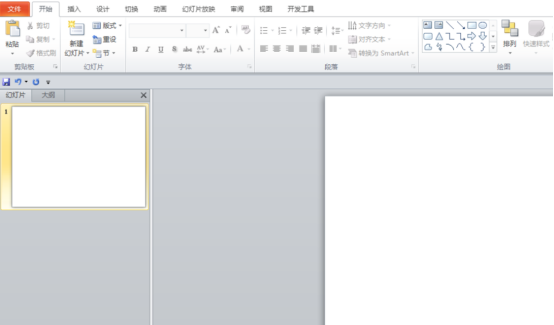 ppt流程图拐弯箭头怎么画Mar 20, 2024 pm 01:20 PM
要说ppt流程图拐弯箭头怎么画?ppt2010能绘制各种各样的箭头,其中一种就是能拐弯的箭头,但是如何去绘制,相信很多人都是不会的,接下来小编就来教大家如何绘制ppt流程图拐弯箭头。想要学习的朋友快来了解一下吧!找到你想要绘制拐弯的箭头的ppt,然后双击打开这个ppt,如下图所示。接着点击【开始】菜单下的【绘图】中的小下三角,如下图所示。然后选择图形中的【弧形】图形,如下图所示。接着直接在幻灯片上绘制一个【弧形】,如下图所示。然后点击上方菜单栏上的【格式】菜单,如下图所示。接着点击【格式】下的【
 使用PHP实现内容管理系统Jun 22, 2023 am 08:13 AM
随着互联网的快速发展,内容管理系统(ContentManagementSystem,CMS)成为了各类网站和应用程序的重要组成部分。通过使用CMS,网站管理员能够更加方便地管理和更新网站的内容,从而提升了网站的用户体验和用户满意度。在本文中,我们将介绍如何使用PHP来实现一个简单的内容管理系统。一、什么是内容管理系统?内容管理系统是一种软件应用程序,它可
 如何使用 Vue 实现流程图制作?Jun 25, 2023 am 09:16 AM
随着互联网的发展,越来越多的应用需要实现流程图的制作,如工作流程图、电路图等。而Vue.js作为一款非常流行的前端框架,提供了极佳的交互性和可维护性,因此被广泛应用于构建复杂的流程图应用程序。本文将介绍如何使用Vue实现流程图制作,包括以下步骤:安装必要的依赖编写基本的组件结构实现拖拽功能实现连接线实现节点编辑导出流程图安装必要的依赖首先,我们需要安
 基于物联网的智能家居系统开发实践May 27, 2023 pm 01:31 PM
随着科技的进步和生活水平的提高,智能家居系统越来越受到人们的青睐。传统的家居设备需要人工控制,而智能家居系统则可以通过物联网技术将各种家电设备、灯光和安防设备等互联互通,实现智能化控制,大大提升居家生活的便利性和舒适度。本文将讨论基于物联网的智能家居系统的开发实践。一、智能家居系统的设计与分析智能家居系统应遵循以下基本原则:安全保障:智能家居系统涉及家庭安
 如何用Python开发CMS系统的报表生成功能Aug 26, 2023 pm 01:09 PM
如何用Python开发CMS系统的报表生成功能随着互联网的不断发展和应用的普及,内容管理系统(CMS)成为了现代化网站开发的基础工具之一。然而,除了管理网站的内容,很多时候我们还需要对网站的数据进行统计和分析,以便更好地了解用户行为和网站运营情况。在CMS系统中添加报表生成功能,可以帮助网站管理员轻松地获取数据分析结果,进一步优化网站的运营策略。本文将介绍如
 PHP中的移动打印管理系统开发指南Jun 11, 2023 am 11:36 AM
随着移动设备的广泛应用,移动打印管理系统在现代化办公室越来越受到重视。在Web开发领域,PHP语言成为了最受欢迎的编程语言之一。本文将介绍如何使用PHP语言开发一个基于移动设备的打印管理系统。一、系统设计与功能分析打印管理系统是一个较为复杂的系统,它需要包含用户管理、打印管理、打印机管理、订单管理等模块。本文仅以打印订单管理为主要分析对象。在系统设计过程中,

Hot AI Tools

Undresser.AI Undress
AI-powered app for creating realistic nude photos

AI Clothes Remover
Online AI tool for removing clothes from photos.

Undress AI Tool
Undress images for free

Clothoff.io
AI clothes remover

AI Hentai Generator
Generate AI Hentai for free.

Hot Article

Hot Tools

Zend Studio 13.0.1
Powerful PHP integrated development environment

Atom editor mac version download
The most popular open source editor

ZendStudio 13.5.1 Mac
Powerful PHP integrated development environment

SublimeText3 Mac version
God-level code editing software (SublimeText3)

Dreamweaver Mac version
Visual web development tools


