

 Computer TutorialsTroubleshootingWhat wires should be plugged into the motherboard when assembling a computer?
What wires should be plugged into the motherboard when assembling a computer?

When assembling a computer, the motherboard is an important circuit board responsible for connecting the various components of the computer. In order for the motherboard to work properly, power cables, data cables, and other peripheral cables need to be connected. Next, we will introduce in detail the cables that need to be connected to the motherboard, including: power cable (24pin and 4pin/8pin); CPU fan cable; chassis front panel cable; graphics card power cable (if necessary); SATA data cable (for connection Hard drive and optical drive); USB data cable (used to connect to the USB interface on the front panel of the chassis). By reading the following, you will understand the connection method and purpose of each wire, helping you to easily complete the computer assembly.

#What wires should be plugged into the motherboard when assembling a computer?
When you assemble your own computer, the connecting cables (all connecting cables) in the chassis are included with the purchased hardware, and there is no need to purchase additional ones.
1. The connection cable between the motherboard and the chassis is brought with you when you buy the chassis, including the front USB cable, boot, restart, hard disk indicator, power indicator, buzzer, etc.;
2. The data cable of the hard disk is brought with you when you buy the motherboard;
3. The cable connecting the host and the monitor is brought with you when you buy the monitor;
4. Some independent graphics cards require a separate power supply. , and when the interface on the old power supply does not match, an adapter cable is required. This is usually included with the graphics card you buy;
5. The others are all included with the power supply.
Extended information:
Additional accessories that need to be purchased by yourself
1. For bulk CPU, you need to purchase an additional radiator.
2. The graphics card and monitor interface do not match each other, so you need to purchase an additional conversion cable.
3. Chassis fan. (The host usually only comes with 1-2 fans. If there are too many, you need to buy extra by yourself)
How to plug in the computer assembly?
1. First insert the 24PIN in the power supply into the 24PIN slot of the motherboard. This item is the mainboard power supply line: after the motherboard power supply connection number.
2. Then there is the CPU power supply. Look at the motherboard. If it is 8PIN, just combine it and insert it. Generally, the CPU power supply is 4PIN. Insert the 4PIN interface in the power supply into the 4PIN slot near the CPU.
3. Then pay attention to whether your graphics card has a 4PIN interface. Generally, low-end graphics cards do not have it.
How to assemble and plug in the computer?
1.
The front panel connections of the chassis generally include front audio, front USB, power indicator light, hard disk indicator light, power on, and restart.
The wiring diagrams for these connections are generally explained in the motherboard manual.
If not, check that it is written on the motherboard. Pay attention to the position of the pins.
They are basically connected in this way. The HD-LED on the motherboard is the hard disk working indicator light, so just write the thread. There are: H..D.D.LED is plugged in. The SP-LED on the mainboard is the power working indicator light. Just plug in the positive and negative ends of the wire with "P" written on it. If the two indicator lights are plugged in reverse, the positive and negative ends are plugged in. Level, the light will not light up after power on. For the one that does not light up, just change the positive and negative directions.
2.
The RST on the motherboard is the reset button. Write RESET on the wire. Plug in the SW. PW-BN on the motherboard is the power-on button. Plug in the one with POWER SW written on the wire.
3.
SPEAKER is the front buzzer, divided into "+" "-" phase; it can happen with ordinary speakers no matter how they are connected, but it is special here. Since the voltage value of +5V is provided on the "+" phase, we must install it correctly to ensure that the buzzer sounds.
4.
The following is the front audio. The F-AUDIO on the motherboard is the location of the front audio interface. It is different from the USB. USB has one less pin on the side. There is one less pin on the 4th pin for audio, just plug it into the corresponding position
5.
The front panel connection is completed, and finally connect the power supply and hard disk. The SATA data cable is in the shape of an inverted 7-digit line. Don’t worry about plugging it in wrongly. If you plug it in wrongly, it won’t go in. The hard drive movie cable is wider than the data cable and has a similar shape. Connect it to the hard drive
6 .
Just align it and insert it. The other end of the SATA data cable is plugged into the SATA interface of the motherboard. That's it, now connect the power supply to the motherboard.
7.
The motherboard is powered by 24P. The old motherboard used to be 20P, so I took it out and there are 4 active ones on the side.
8.
The CPU has 8P power supply, and there are also 4P power supply. Both the motherboard and CPU power supply are designed to be fool-proof. Don’t worry about plugging it in wrongly. If you plug it in the wrong direction, you won’t be able to plug it in.
9.
Connect to the corresponding interface. Look at the motherboard interface diagram above. The graphics card power supply is 6P, and there are also 8P. It can be disassembled, and the graphics card power interface is plugged in. That's it.
10.
The installation is complete. If your case is side-transparent, you can install a strip of polarizing light, which will look much better. If it is not side-transparent, there is no need to install it. You are good to go. For a chassis with back-line cables, put the cables at the back so it looks nice. After installation, untie the cables and tie up the ones that need to be tied up with zip ties to make it look more comfortable.
Computer assembly--How to connect the motherboard and the front panel cable of the host?
1 USB is a set of 8-wire 10-hole plugs. The side with the black wire should be inserted in the direction of one less pin on the motherboard. 2 RST pins are connected to the panel reset button. PO-ON pins. Connect the panel power-on button (no requirement if plugged in)
3 HD-LED is the hard disk read and write indicator light (note that if the positive and negative poles are plugged in, if they don’t light up, just reverse them)
4 PWR-LED is the host power indicator light·(Note that if the positive and negative poles are plugged in, if they do not light up, just reverse them.) 5 SPEAKER is the buzzer pin. The black wire is negative and the red wire is positive·6 Panel headset· The motherboard pins are a row of 10-pin double-row pins. The second pin in one row is missing one pin. It is actually 9 pins. The panel connection plug is a set of 5-wire or 7-wire 10-hole plugs, one or two of which are Empty·(no wires), just insert it in the direction with one less pin on the motherboard··
How to connect the wires to the computer motherboard?
Computer motherboard wiring insertion method:
1. Insert the power supply and find the needle and wire
Insert the power supply into the chassis. In the power cord, find the 24 for the motherboard power supply. sewing.
2. Insert the power cord into the motherboard
Insert the power cord into the motherboard and pay attention to the position of the power cord's bayonet.
3. Find the interface power cable and connect it to the motherboard
Find the 4-port cable for the motherboard power supply and the CPU power interface, and connect the power cable to the motherboard.
4. Connect the hard disk cable to the power interface
Find the hard disk power cable and connect it to the power interface of the hard disk.
5. Connect the SATA cable to the interface
Plug another SATA power cable into the power interface of the optical drive.
How to plug in the power cord when assembling a computer?
1. Take out the motherboard, remove the CPU and install it, fix the fan, plug in the memory and put it away.
2. Remove the covers on both sides of the chassis, install the power supply, and screw the motherboard tray screws in the chassis to the designated position.
3. Handle the motherboard baffle according to the interface position, snap it into the chassis back bezel, put the motherboard correctly into the chassis, and gently tighten the screws. For independent graphics, break off the small PCI-E baffle, insert the graphics card and secure it with screws.
4. Plug in the 24+4-pin power cord. If the 4-pin cord is too long, tie it into a knot.
5. Separate the front USB and audio jack cables with USB and AUDIO letters on the back from the chassis, and insert them into the USB pin slot and AUDIO pin slot of the motherboard respectively. Both are to prevent mis-insertion. The USB pin slot is usually in the lower right corner of the motherboard, and there is a USB mark under the pin slot. The AUDIO pin slot is generally located in the middle and lower left side of the motherboard.
6. Knot the switch, restart, hard disk indicator light and other wires on the chassis. Generally, this type of plug on the motherboard is adjacent to the USB. In the lower right corner of the motherboard, there are letters marking the corresponding plugs on the motherboard, such as HDLED. is the hard disk indicator light, RST is the cold start, POW-SW is the startup, SPEAKER is the alarm horn, and POW-LED is the power indicator light. Just plug them in one by one.
7. Remove the baffle at the optical drive position of the chassis (the card head can be pushed out from the back and removed). Put the optical drive in and secure it with screws.
8. Take out the optical drive and hard disk data cable. If it is a parallel port data cable, please confirm that there is an IDE interface on the motherboard. The serial port cable is generally longer. After forming a spiral shape with your fingers, you can insert it into the motherboard serial port port in sequence, and then plug in the optical drive and hard disk power cables.
9. Use tying thread to gather and fix the messy threads appropriately. Install the side covers in sequence. You're done, the next step is to partition the hard drive and create a system.
Purely personal experience, let’s discuss the shortcomings together. Reproduction is prohibited.
How to plug the computer cable into the motherboard?
The method of plugging the computer's cable into the motherboard depends on the type of cable you want to connect. Here are some common cable types and how to plug them in:
1. Power cable: The power cable is the cable that connects the power supply to the motherboard. It usually has a 20-pin or 24-pin connector. Plug the power cord into the power socket on the motherboard, making sure the connector is oriented correctly, and then gently press the connector until it is fully inserted.
2. Data cable: The data cable is a cable that connects hard drives, optical drives and other devices to the motherboard. It usually has a SATA or IDE interface. Insert the data cable into the corresponding port on the motherboard, making sure the connector is oriented correctly, and then gently press the connector until it is fully inserted.
3. USB cable: A USB cable is a cable that connects a USB device to the motherboard. It usually has a USB interface. Insert the USB cable into the USB port on the motherboard, making sure the connector is oriented correctly, then gently press the connector until it is fully inserted.
4. Monitor cable: The monitor cable is the cable that connects the monitor and the motherboard. It usually has a VGA, DVI or HDMI interface. Plug the monitor cable into the corresponding connector on the motherboard, making sure the connector is oriented correctly, and then gently press the connector until it is fully inserted.
It should be noted that before plugging in the cable, you should turn off the computer and unplug the power plug to avoid electric shock and damage to the equipment. In addition, be careful when inserting the cable to avoid damaging the connector due to excessive force.
How to plug in the computer motherboard audio cable?
How to plug in the audio cable on the computer motherboard, find the audio socket
There are three round sockets on the back of the host, among which the bright green socket in the middle is the audio output socket
2
Insert the plug
We now insert the round plug into the middle round socket
3
Insert the USB
In addition, plug the USB port into any USB port behind the host machine
4
Select the front speaker according to the prompts
You will see a prompt before returning to the monitor, select input Device type, select the front speaker, click OK
5
Turn on the audio switch to complete
Turn on the audio switch, see that the audio device has lights on, and the sound can be output normally
How to plug in the computer motherboard startup cable?
The method of plugging the motherboard power-on cable is: Plug the power-on cable into the switch jack on the motherboard, usually near the power jack. When inserting, pay attention to the front and back of the jack. Generally, a black interface is inserted into a black one. Jack, the red interface is inserted into the red jack. After confirming that the insertion is correct, turn the switch to the "on" position to turn on the phone.
How to plug the computer boot cable into the motherboard?
1. First, connect the power cord from the chassis. One of them is relatively wide. If it is marked USB, then it is the cable connecting the USB socket on the chassis panel. On the motherboard On the edge, look for the USB pin and plug it in.
2. In the wiring harness in the chassis, if you see a wire marked HDD_LED, then this is the wire for the disk’s working indicator light, which is consistent with the corresponding HDD_LED pin on the motherboard. Just pick it up.
3. When you see a line marked Power_SW, connect it to PWR_BTN. The position of PWR_BTN on the motherboard and HDD_LED are marked in upper and lower rows. Some are marked PWR_SW, but they all refer to the host power switch line; POWER_LED is the indicator light, just connect it to PWR_LED.
4. In addition to these, there is also a more important motherboard wiring in the host, which is the restart switch line. This line is marked RESET_SW on the head.
5. On the motherboard, find the pin marked RESET. Because it is marked in rows, it is the two pins in the lower row. Just plug it in.
The above is the detailed content of What wires should be plugged into the motherboard when assembling a computer?. For more information, please follow other related articles on the PHP Chinese website!

 Clipchamp Video Loss on Windows? 2 Ways to Recover Files!May 09, 2025 pm 08:12 PM
Recover Lost Clipchamp Videos: A Step-by-Step Guide Losing a video you've edited in Clipchamp can be frustrating. This guide provides effective methods to recover your lost Clipchamp video files. Finding Your Clipchamp Videos Before attempting recov
 7 Useful Fixes for Action Center Keeps Popping upMay 09, 2025 pm 08:07 PM
Action Center allows you to access quick settings and notifications. However, some users say that they encounter the “Action Center keeps popping up” issue on Windows 11/10. If you are one of them, refer to this post from MiniTool to get solutions.Qu
 Instant Ways to Restore Missing Google Chrome Icon on WindowsMay 09, 2025 pm 08:06 PM
Troubleshoot Missing Google Chrome Icon on Windows Can't find your Google Chrome icon on Windows? This guide offers several solutions to restore it. Why is my Chrome icon missing? Several factors can cause the Chrome icon to vanish from your desktop:
 Brave Browser High CPU and RAM Usage: Best 5 Tips to ReduceMay 09, 2025 pm 08:05 PM
Brave browser CPU and memory usage too high? Under Windows 10/11 system, Brave browser's high CPU and memory usage problems have troubled many users. This tutorial will provide a variety of solutions to help you easily resolve this issue. Quick navigation: Brave browser high CPU and memory footprint Solution 1: Clear cookies and cache data Solution 2: Disable hardware acceleration Solution 3: Close the tab and update the Brave browser Solution 4: Disable the plugin Solution 5: Create a new user profile Optional: Run MiniTool System Booster System Optimization Tool Summarize Brave browser high CP
 Targeted Fixes for Xbox Error 0x87e0000f When Installing GamesMay 09, 2025 pm 08:04 PM
Troubleshooting Xbox Error Code 0x87e0000f: A Comprehensive Guide Encountering the Xbox error code 0x87e0000f while downloading games from Xbox Game Pass can be frustrating. This guide provides several solutions to help you resolve this issue and get
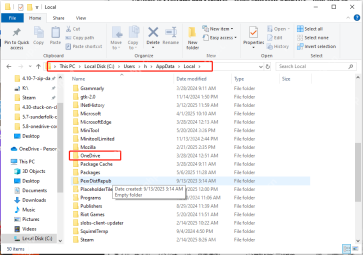 OneDrive Couldn't Start Files on Demand?Top 4 MethodsMay 09, 2025 pm 08:02 PM
OneDrive Files On-Demand troubleshooting: resolving the "OneDrive couldn't start Files On-Demand" error. This MiniTool guide provides solutions for the persistent "Microsoft OneDrive Couldn’t start files on Demand" error (codes 0x
 How to fix 'Microsoft Store is blocked' error in Windows?May 09, 2025 pm 06:00 PM
Microsoft Store is blocked error occurs when Windows prevents access to the Microsoft Store app, displaying the message Microsoft Store is blocked. Check with y
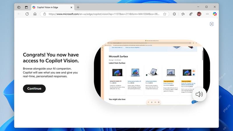 How to use Copilot Vision for free in Microsoft EdgeMay 09, 2025 am 10:32 AM
Staying current with all the new AI tools is a challenge. Many might even overlook readily available AI features. For instance, Copilot Vision is now free for all Microsoft Edge users – a fact easily missed if you don't regularly use Edge or haven't


Hot AI Tools

Undresser.AI Undress
AI-powered app for creating realistic nude photos

AI Clothes Remover
Online AI tool for removing clothes from photos.

Undress AI Tool
Undress images for free

Clothoff.io
AI clothes remover

Video Face Swap
Swap faces in any video effortlessly with our completely free AI face swap tool!

Hot Article
Hot Tools

SublimeText3 English version
Recommended: Win version, supports code prompts!

SublimeText3 Mac version
God-level code editing software (SublimeText3)

Safe Exam Browser
Safe Exam Browser is a secure browser environment for taking online exams securely. This software turns any computer into a secure workstation. It controls access to any utility and prevents students from using unauthorized resources.

EditPlus Chinese cracked version
Small size, syntax highlighting, does not support code prompt function

SublimeText3 Chinese version
Chinese version, very easy to use

